


EUR
en
SuctionBoiler feedwater from the deaerator is drawn into the pump through this pipe.
BearingThe type of bearing used depends upon the pump design. Due to the usage of multiple impellers, some axial thrust is transferred to the bearings. Thus a suitable bearing should be chosen to handle both axial and radial thrusts.
Mechanical SealMechanical seals are used to seal the space between the pump shaft and casing. The seal prevents boiler feedwater leaking out of the intended flow area.
Pump ShaftThe pump shaft is installed through the centre axis of the pump. The impellers, mechanical seals and bearings are all installed onto the shaft. Shaft keys are used to mechanically connect each impeller to the shaft.
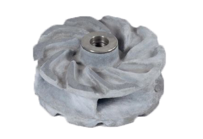
1st Stage ImpellerThe first centrifugal impeller that the feedwater comes into contact with is referred to as the 1st stage impeller. This pump has five impellers (five stages).
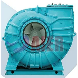
CasingThe casing must withstand the high system pressures to which it is subjected, as well as high temperatures. A boiler feedwater pump will typically discharge at pressures exceeding several hundred bar (>2900 psi), the casing must be able to withstand this pressure.
DischargeAfter passing through several centrifugal pump impeller stages, boiler feedwater is discharged through this pipe.
Various trade organizations have presented data suggesting that pumping systems account for roughly 20% of the worlds electrical energy demand. There have also been figures presented stating that 85 percent of the total cost of ownership of a pumping system is the cost of the electrical energy to operate the system.
Steps taken to improve the efficiency of these pumping systems would result not only in operating cost savings, but in reduced energy consumption and reduced load on electrical energy supply sources. One step that should be considered when evaluating the efficiency of a traditional single- stage pump installation is the use of multi-stage technology.
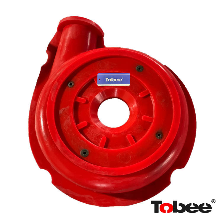
Single-stage pumps use a single impeller and volute to generate pressure. The amount of pressure generated by the impeller/volute combination depends on the diameter of the pump impeller, and the speed at which the impeller is turning. For a single-stage pump, the impeller is the sole element for transferring energy to the pumped liquid. The impeller can only impart energy into the pumped fluid as long as it is in contact with the fluid, so the diameter of the impeller is very important in determining the performance of the pump.
Various operating points within the hydraulic performance envelope of the pump are met by trimming (reducing) the diameter of the impeller. This reduces the energy transferred into the pumped liquid, subsequently reducing the head developed by the pump. The distance shown in Figure 1 between the edge of the impeller and the volute is important in determining the pump hydraulic efficiency.
For a specific pump size, there is an optimum impeller diameter where the pump will run at its best efficiency. There is also a flow rate and head where the pump will operate at its Best Efficiency Point (BEP).
For all other operating points within the flow and head envelope covered by this pump, the pump needs to be controlled via speed control, the impeller diameter needs to be reduced, or both. In looking at the pump curve in Figure 2, operating away from the BEP results in significant reduction in pump efficiency.
The shape of the pump curve is also noteworthy, especially when trying to apply variable speed pump control. When using speed to control the operation of a pump, as the speed of the pump is reduced, the curve that the pump operates on shifts down and to the left, reducing the flow and head produced by the pump. The Affinity Laws show how a pump’s performance changes with changing pump speed (RPM).
When a pump has a flat curve as shown in Figure 2, a relatively small change in pressure produces a large change in flow, making control via pressure difficult, and limiting the amount of speed reduction available. The Affinity Laws state that the horsepower drawn by a pump varies by the cube of the difference of the speed. The limited speed reduction available to pumps with flat performance curves also limits the horsepower reduction (energy savings) that can be achieved using speed control.
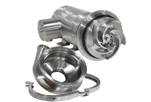
Multi-stage pumps use multiple impellers and volutes in series to achieve pressure. The pumped fluid is discharged from an impeller and volute (called a stage) and immediately enters the next impeller and volute.
The amount of pressure developed in a multi-stage pump depends on the diameter of the impellers, the number of stages used, and the speed at which the impellers are turning. In multi-stage pumps, the diameter of the impellers is usually not trimmed to achieve the required operating conditions.
Additionally, because there are multiple impellers used to impart the energy required into the pumped liquid, each impeller/volute combination can be smaller in diameter and operate with a smaller gap between impeller and volute (see Figure 1). Because of this tight clearance between impeller and volute, multi-stage pumps are not recommended for applications pumping liquids containing solids, abrasives, or stringy material. The result of this tight tolerance between impeller and volute is that each impeller operates close to its best hydraulic efficiency. What is varied to meet different operating conditions is the number of impellers used in the multi-stage pump.
Figure 5 below shows how various operating conditions within the hydraulic performance envelope of a multi-stage pump are met. If more pressure is required, more stages (impeller/volute combinations) are added, if less pressure is required, a pump with fewer stages is selected.
As with the single-stage pump, the shape of the curve is important, especially when controlling the operation of the multi-stage pump via speed control. When trying to control the operation of a pump based on the system pressure, it is easier to control a pump with a steep curve versus a pump with a flat curve. Unlike a pump with a flat curve, a pump with a steep curve will not have as large of a change in flow for the corresponding small change in pressure. The available turn-down of a pump with a steep curve is more than the available turn-down of a pump with a flat curve.
Remembering from the Affinity Laws that horsepower drawn by the pump varies by the cube of the difference in speed, a pump with a steep performance curve can realize more energy savings when controlled by speed versus a pump with a flatter performance curve.
Figure 6 shows both a single-stage and a multi-stage pump were selected for the same operating point. During the operation of these pumps, there is a reduced flow condition that the pumps must operate at.
Using variable speed, the turn down available for the single-stage pump is only about 5% (3,319 rpm vs. 3,500 rpm). Likewise, the turn down available for the multi-stage pump is over 17% (2,882 rpm vs. 3,500 rpm). The difference in speed results in a 37% increase in energy reduction at the reduced operating condition.
Traditionally, changing from a single-stage to a multi-stage pump requires considerable changes to piping and pump supports. Advances in product design have resulted in multi-stage pumps that have pump suction, discharge, and mounting dimensions that are interchangeable with ANSI-dimensioned pumps.
With the decreased energy required using multi-stage technology, the size of the motor needed to drive the multi-stage pump is often much smaller than the motor required by the single-stage pump. The overall effect is that while the pump itself may be longer because of the additional stages required to meet the system operating conditions, the decrease in the motor size offsets in the increased pump length, and the overall pump and motor foot print is usually less than that of a single-stage pump and motor. .
When looking to optimize pump efficiency, serious attention should be paid to the prospect of multi-stage technology. Because of their design, multi-stage pumps offer several advantages over single-stage pumps. Multi-stage design allows for smaller diameter impellers, permitting them to operate at higher efficiency than the majority of single-stage pumps.
The steep curve of a multi-stage pump makes using pressure to control the speed of these pumps easier than controlling single-stage pumps with flatter curves. Finally, the curve of the multi-stage pump allows for greater turn-down when using speed to control the pump, and as the Affinity Laws state, greater speed reduction results in greater reduction in brake horsepower.
Pump users of today are experiencing increasing pressures from within their own organizations and from external sources, to conserve energy, cut operating costs, and increase energy efficiency of the systems they operate. Multi-stage technology offers several advantages over traditional single-stage pumps when used to pump liquids that do not contain abrasives, solids or stringy material.
Recent developments in multi-stage technology have eliminated the need for piping and pump support rework when retrofitting a multi-stage pump for a single stage pump, making it easier than ever to consider multi-stage pump replacement of traditional single-stage pumps.
A multistage pump pressurizes the fluid in more than one stage. Each stage contains an impeller and a diffuser. Therefore, it has more than one impeller. These impellers can be of the same type or of different types.
The multistage pumps have multiple impellers and diffusers to increase the fluid pressure instead of pistons.
The main objective of the impeller is to increase the speed of the fluid. In contrast, the diffuser converts the fluid speed into pressure and increases the fluid pressure. This is a more efficient pump than the single-stage pump. It produces more pressurized fluid than the single-stage pump.
A multistage pump works on the angular momentum principle. It uses centrifugal force to move the fluid in and out of the pump. In this pump, the fluid (i.e., water) flows from different stages. It works in the following way:
The multistage pump has the following major types:
The vertical multistage centrifugal pump is installed vertically. Therefore, these pumps require more installation space in the vertical direction. However, you can easily install them in an area where you have very low space in the horizontal direction.
This pump has a vertical shaft on which stages stack on one another. It is ideal for areas with limited space. Another advantage of this pump is that a combination of a single pump body and a motor can supply a high-pressure output.
However, it is important to remember that these types of multistage pumps can’t transfer contaminated fluids and large amounts of solids.
They have a small clearance. The applications of the vertical pumps are given below:
A horizontal multistage pump is installed in a horizontal direction. It contains a segmented body with modular components between the stages. The rotating components of the pump are fixed between the bearing seats, which enhances the balancing of the rotating components under high-pressure conditions. This configuration of the pump prevents it from extreme vibration.
The main disadvantage of the horizontal multistage pump is that it needs more floor space in the horizontal direction. However, it has the capability to control more flow rates than a vertical multistage pump (without vertical turbo pumps).
The horizontal multistage pumps are ideal for the following applications:
However, this pump requires more maintenance than the vertical multistage pump. The operator needs good knowledge to operate the horizontal pump. According to the brand type and the quality of the construction materials, these pumps may have high initial costs.
Single-Stage PumpMultistage PumpA single-stage pump pressurizes the fluid in just one stage.A multistage pump pressurizes the fluid in more than one stage.It has only one impeller and diffuser.It has multiple impellers and diffusers.This pump has lower rotating parts than the multistage centrifugal pump.It has more rotating parts than the single-stage pump.These pumps require low space for installation.They require large installation space.They are less efficient.They are the most efficient.A single-stage pump has easy maintenance and operation.It has complex operation and maintenance.It has a low maintenance cost.This centrifugal pump has a high maintenance cost.It requires low maintenance.It needs high maintenance.It can’t handle much fluid as multistage.It has the capability to handle a large amount of fluid.
What are the types of Multistage Pumps?
The multistage pumps have the following types:
What are the multistage pumps used for?
The multistage pumps are used for different applications including:
Bookmark
Daniel Féau processes personal data in order to optimise communication with our sales leads, our future clients and our established clients.


This site is protected by reCAPTCHA and the Google Privacy Policy and Terms of Service apply.