


EUR
en
This section presents design and construction guidance of private and public sewage pump stations. The design and construction of sewage pump stations shall confirm to the Washington State Department of Ecology’s Criteria for Sewage Works Design , latest edition, and these Standards.
A. Air/Vacuum Release Valve: An air valve placed at the high points of a pipeline to release the air automatically and prevent the pipeline from becoming air-bound with a resultant increased head loss. The valve will also allow air into a pipeline in the event of a vacuum condition caused by a main break or surge event.
B. Average Design Flow: The average daily flow of the maximum month.
C. Backflow Prevention Device: Any effective device, method or construction used to prevent backflow into a potable water system.
D. Bar Screen: A rack composed of parallel bars, either vertical or inclined, placed in a waterway to catch debris.
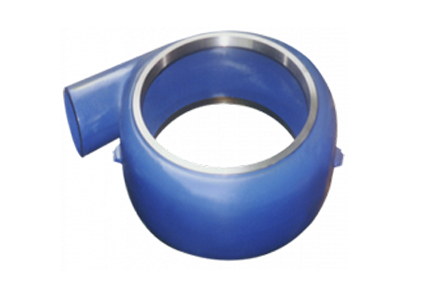
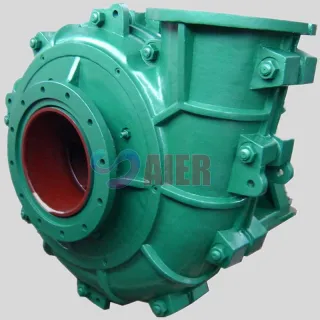
E. Centrifugal Pump: A pump consisting of an impeller fixed on a rotating shaft and enclosed in a casing and having an inlet and a discharge connection. The rotating impeller creates pressure in the liquid by the velocity derived from centrifugal force.
F. Datum Reference: Point for all readings for suction lift, suction head, total discharge head (TDH) and net positive suction head (NPSH). For horizontal shaft pumps, the datum elevation is the pump centerline. For vertical shaft pumps, the datum elevation is the elevation of the entrance eye of the suction impeller.
G. Force Main: A pipeline that conveys wastewater under pressure from the discharge side of a pump to a discharge point.
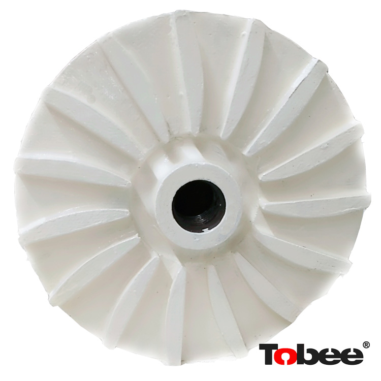
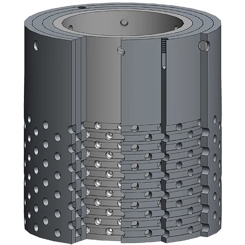
H. Impeller: A rotating set of vanes designed to impel rotation of a mass of fluid.
I. Net Positive Suction Head (NPSH): The total suction head, in feet of liquid absolute, determined at the suction nozzle, less the vapor pressure of the liquid in feet absolute.
J. Peak Design Flow: The largest estimated flow rate sustained over a 60-minute period in the design year of the pump station.
K. Pump Station: A pump station that pumps wastewater to a higher elevation when the continuance of the sewer at reasonable slopes would involve excessive depths of trench (depths where repair or replacement would require special or costly construction techniques).
L. Static Head: The difference in suction and discharge water levels, does not include dynamic losses.
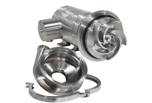
M. Submersible Pump: A pump that is designed to be submersible and is placed in a pit that needs pumping out. Submersible pumps push fluid to the surface.
N. Suction Head: Suction head exists when the total suction head is above atmospheric pressure. As determined on test, it is the reading of the gage at the suction of the pump converted to feet of liquid and referred to datum, plus the velocity head at the point of gage attachment.
O. Suction Lift: Suction lift exists when the total suction head is below atmospheric pressure. Total suction lift, as determined on test, is the reading of a liquid manometer at the suction nozzle of the pump converted to feet of liquid and referred to datum, minus the velocity head at the point of gage attachment.
P. Sump: A tank or pit that receives wastewater and stored is temporarily, and from which the wastewater is pumped or ejected.
Q. Total Discharge Head: The reading of a pressure gage at the discharge of the pump, when the pump is in operation, converted to feet of liquid and referred to datum, plus the velocity head at the point of gage attachment.
R. Total Dynamic Head (TDH): Also called “total head .” TDH is the measure of energy increase per pound of the liquid imparted to it by the pump. Where suction lift exists, TDH is equal to the sum of the total discharge head and total suction lift, and, where positive suction head exists, TDH is the total discharge head minus the total suction head.
S. Velocity Head: The theoretical vertical height to which a liquid body may be raised by its kinetic energy. It is equal to the square of the velocity divided by twice the acceleration due to gravity (v2/2g).
T. Water Hammer: The phenomenon of oscillations in the pressure of water about its normal pressure in a closed conduit, flowing full, that results from a too-rapid acceleration or retardation of flow. Momentary pressure greatly in excess of the normal static pressure may be produced in a closed conduit by this phenomenon.
U. Wet Well: A compartment in which wastewater is collected, and; (a) to which the suction pipe of a pump is connected, or (b) in which a submersible pump is installed.
A. Justification for any proposed pump station is required which clearly exhibits that gravity lines are not available and not economically feasible.
B. The number of pump stations for each basin shall be optimized.
C. Sewage pumping stations and force mains are to be provided solely for the conveyance of sanitary wastes. Under no circumstances shall any roof, foundation, surface or subsurface drainage, or any other form of storm drainage be allowed to pass through the proposed facilities.
D. Private grinder pumps are only permitted under special circumstances when no other means of sewer service is available. In general, gravity sewer shall be deepened to eliminate the need for grinder pumps. Use of private grinder pumps requires approval by the Town and will be evaluated on a case-by-case basis. Applicant will need to demonstrate that there is no other feasible means of servicing lot/lots for acceptance.
E. Private pump stations shall not serve more than one property. Private pump stations are only allowed where gravity sewer exists adjacent to a property, but is not deep enough to serve all of the property. Private pump stations may be allowed where an existing condition could present a health hazard. Private pump stations shall be a Liberty packaged grinder pump. The Town may approve other domestically made packaged grinder stations with parts and service that are readily available. Submit product information for the specific unit being proposed to the Town for review and approval.
F. Private and public pump stations must meet established minimum standards provided herein. Public pump stations will only be approved on a case-by-case basis. Only public pump stations will be maintained and operated by the Town.
G. A pump station serving multiple parcels in a new development created by a short plat shall be dedicated to the Town and deemed public. Such pump stations shall be a Liberty grinder pump packages of appropriate size.
H. All pump stations serving parcels of a new development created by long plat or master planned commercial development shall be dedicated to the Town and deemed a public pump station. Each shall be site built pump stations specifically designed for the application meeting the Town requirements stated herein.
I. Due consideration shall be given to the selection of all materials used in the construction of sewage pump stations, because of the presence of hydrogen sulfide and other corrosive gases, greases, oils, and other constituents frequently present in sewage.
A. The Project Engineer shall submit all supporting documentation, in report form, including all relevant design information needed to justify the need for the pump station and for the Town to review for adequacy of the proposed design. The design of any pump station shall conform to Washington State Department of Ecology’s latest edition and applicable standards as set forth herein. The design report shall be submitted with each pump station and shall demonstrate its conformance with the Standards as outlined herein. The report is to be stamped by an engineer, licensed in the State of Washington. At a minimum the following shall be submitted.
1. The pump station design must have a minimum of two pumps
2. Design flow analysis (break down of phases if applicable) including peak sewage flow calculations.
3. All relevant elevations, such as; pump(s) off, discharge elevation, pumps(s) on, alarm elevation, max allowable storage elevation, etc. Maximum static head
5. Force main size and length
6. Pump station capacity (gpm) per each pump and multiple pumps
7. Velocity within force main
8. System head and pump curves (including compound pump curves when applicable)
9. “C” values (Hazen Williams coefficient) for force mains
10. Friction head loss (calculations)
11. Velocity head
12. Total dynamic head
13. Pump time/cycle and number of cycles per day
14. Storage available and storage required during a power outage scenario (min and max time)
15. Discussion of odor control
16. Water hammer calculations
17. Buoyancy calculations (if there is potential for high groundwater)
18. Pump station specifications (generator specifications if applicable)
19. Pump(s) specifications
20. System back up plan (i.e. storage method, alternate power source)
21. Maintenance Agreement (for private storage)
22. Wiring Schematic in addition it shall be the Project Engineer’s responsibility to make all technical submittals to Washington Department of Ecology and obtain Ecology project approvals.
A. System head curves with over laid selected pump curves shall be provided in each engineering design report. Data points for the system capacity curve shall be provided in tabular form and graphed with pump head capacity curve on the same axis. System capacity curves shall be plotted using the Hazen Williams coefficient values of C=100 and C=130.
B. Pump output in gpm at maximum and minimum head shall be clearly shown on system curves for each pump and combination of pumps.
C. For stations with two or more pumps operating in parallel, multiple and single operation points shall be plotted on the system head curve.
D. Pumps with the best efficiencies at all operating points shall be chosen.
E. If a station is equipped with smaller impellers during start-up to handle lower than design flows, impellers sized to handle the design flow shall also be provided.
F. Pump systems shall meet the peak flow criteria with the largest pump out of service.
A. Location
1. A pump station site shall be selected to serve the entire basin, considering ultimate build-out of the basin.
2. In selecting a pump station site, consideration shall be given to minimizing its aesthetic, noise, and odor nuisance potential. A buffer zone between the pump station and its surrounding environment shall be provided. Buffer zones shall be designed to allow the pump station to blend into the surrounding environment and provide noise mitigation.
3. The pump station site shall be readily accessible by maintenance vehicles during all weather conditions. The facility should be located off the traveled way of streets and alleys. The grading and hardscape immediately adjacent the pump station structure shall allow direct truck access for removal and replacement of pumps by truck mounted hoist.
4. The pump station site shall be large enough for all equipment and have sufficient parking for maintenance vehicles. The minimum pump station site shall be .25 acre.
A. The pump station structures, electrical and mechanical equipment shall be designed to sustain no physical damage by the 100-year flood. The station should remain fully operational and accessible during the 25-year flood.
A. All sewage pump stations shall be submersible pump stations. Suction lift, screw type or pneumatic ejector are not allowed.
B. The design of any pump station shall conform to these Standards, Department of Ecology’s Criteria of Sewage Works Design and applicable standards as set forth herein. In addition, the plans shall include the following;
C. An overall site drawing of the pump station showing the location of all components including elevations;
D. Electrical service size, voltage, and enclosure type and location in relation to the pump station;
E. A list of specific materials used including quantity description and manufacturer name;
F. A schematic and line diagram of the service and motor control center and pump station;
G. The electrical and control systems shall be designed to meet state and local electrical code requirements;
H. An operation and maintenance manual from the pump station contractor shall be supplied;
I. Pump operation, alarms, and electrical inspection of all pump stations is required.
J. Pumping Rate and Number of Units
1. At least two pump units shall be provided, each capable of handling the expected peak design flow.
2. Where three or more units are provided, they shall be designed to fit actual flow conditions and must be of such capacity that with any one unit out of service, the remaining units will have the capacity to handle the peak design flow.
3. When the station is expected to operate at a flow rate less than 0.5 times the average design flow for an extended period of time, the design shall address measures taken to prevent septicity due to long holding times in the wet well.
K. Grit and Clogging Protection
1. Where it may be necessary to pump sewage prior to grit removal, the design of the wet well should receive special attention, and the discharge piping should be designed to prevent grit settling in pump discharge lines of pumps not operating.
L. Pumping Units
1. Type of Pumps: See Section 5.9 Submersible Lift Stations.
2. Priming: Pumps shall be so placed that under normal operating conditions they will operate under a positive suction head.
3. Operation Controls: Provisions should be made to automatically alternate the pumps in use. Pump station controls shall be above grade and should be equipped with a secure external disconnect switch. The motors and controls shall be securely housed to the satisfaction of Public Works.
M. Flow Measurement
1. A magnetic flow meter for measuring sewage flow shall be provided at all pumping stations. Provide a separate vault for the flow meter. Vault shall meet requirements of NFPA 820.
N. Bypasses
1. Provisions may be made for controlled bypasses, if necessary to avoid excessive property or equipment damage. The controlled bypass shall be manually operation valve or plate covering the bypass discharge, and shall act as a pump connection port.
O. Alarm System
1. An alarm system shall be provided for all public and private pumping stations. Public lift stations shall facilitate a telemetry alarm to 24-hour monitoring stations or telephone alarms to Town personnel. And the Town ’s SCADA system. For private lift stations when telemetry is not used, an audio-visual device should be installed for external observation.
2. Alarms for high wet well, low wet well, and power failure shall be provided, as a minimum, for all pump stations. Alarms signalizing pumps and other component failures or malfunctions may also be required.
3. A backup power supply, such as a battery pack with automatic switchover features, shall be provided for the alarm system, such that a failure of the primary power source will not disable the alarm system. Test circuits shall be provided to enable the alarm system to be tested and verified as in good working order.
P. Materials Considerations
1. Consideration shall be given to the presence of hydrogen sulfide and other corrosive gases, greases, oils, and other constituents frequently present in sewage. With the exception of the pumps, pipe and wiring, metal materials located in areas subject to such conditions shall be stainless steel (guide rails, fasteners, cable, etc.)
Q. Electrical Equipment
1. Electrical systems and components (e.g., motors, light, cables, conduits, switchboxes, control circuits) in enclosed or partially enclosed spaces where flammable mixtures occasionally may be present (including raw sewage wet wells) shall comply with the National Electrical Code and NFPA requirements for Class 1 Division 1 locations.
R. Electrical Control Panel
1. The electrical control panel for public and private lift stations shall be located in a control enclosure, cabinet or building designed to blend aesthetically with the surroundings. The electrical control panel for the public lift stations shall be provided with the minimum following items:
a. An Allen Bradley PLC Supporting alarm outputs and SCADA access, compatible with the Town’s existing system
b. Wet well level sensor system
c. Hand-off-automatic selector switch, each pump
d. Lag, lead and automatic pump selector switch
e. Elapse time indicator, each pump
f. Ammeter, each pump
g. Run indicator lights, each pump
h. Pilot light indicator for each and every alarm, automatic shut-down and running condition
i. Alarm reset and test button
j. Outside mounted red alarm light
k. 110 volt convenience outlet
l. Control power available indicator light
m. Alarm system per Section 5.8 O
n. Alarm horn
S. Service Wiring
1. Underground wiring shall be provided between the pump station and nearest power pole or pad mounted transformer (sectionalizer) if underground power is available.
T. Telemetry
1. Town will provide , at the applicant/subcontractor’s expense, telemetry equipment for contractor’s installation .
U. Lighting
1. Adequate interior and exterior lighting for the entire pump station shall be provided. Explosion proof is generally required.
V. Water Supply
1. There shall be no physical connection between any potable water supply and a sewage pumping station which under any conditions might cause contamination of the potable water supply. Potable water supply brought to the station shall comply with conditions stipulated in the Washingto n State Department of Health’s Criteria for Accepted Cross Connection Control Assemblies. A minimum 1 inch water line with a reduced pressure backflow assembly, with a hot box enclosure, shall be installed near the pump station for station cleaning purposes. The water service line shall be provided with a frost-free hydrant, hose, rack and nozzle for pump station wash down.
W. Pump and Motor Removal
1. Provisions shall be made to facilitate removing pumps, motors, and other equipment, without interruption of system service.
X. Access
1. Suitable and safe means of access should be provided to equipment requiring inspection or maintenance. All permanent pump stations shall be provided with lockable hatches.
Y. Valves and Piping (Site-Built Stations)
1. Shutoff valves shall be placed on discharge lines of each pump in the valve vault (as applicable) for normal pump isolation. A check valve shall be placed on each discharge line, between the shutoff valve and the pump. Pump suction and discharge piping should not be less than 4 inches in diameter except where design of special equipment allows.
a. Check valves. Check valves used on pump stations shall have adjustable tension levers and spring. It shall have a working pressure of 150 psi. Valves shall be designed for use with corrosive fluids. A check valve shall be installed in a valve vault located adjacent to the pump station ’s wet well. Check valves shall conform to AWWA standards. Valves shall be mounted horizontally where space permits. Suitable shutoff and check valves shall be placed on the discharge line of each pump in a wet pit pump station configuration. The check valve shall be located between the shutoff valve and the pump, and shall not be placed on the vertical portion of discharge piping. The seats of all check valves shall be removable without removing the valve itself. Suitable rising stem shutoff valves shall be placed on the discharge of each pump in a wet pit pump station configuration.
b. Valve box lids may be used for isolation valves on a force main. Valve box lids shall be specified to be marked with “SEWER” so they can quickly be distinguished from valves in the water system.
c. All station shall be 4-inch flanged ductile iron. Flexible coupling shall be used on all pump discharges. Other couplings shall be used to provide flexibility in re-assembling piping.
Z. Odor Control and Ventilation
1. The effect of odor on adjacent land use and workers shall be assessed. Every effort shall be made in site selection to reduce potential odor pollution. Wind direction, duration and intensity are all important considerations that must be evaluated.
2. Odor control shall be provided if there is no station inflow for 6 hours or, if the wet well (wet pit) detention time exceeds 6 hours.
A. All Town of Friday Harbor sewage pump stations shall be of the submersible pump type. Submersible pump stations shall meet the following requirements:
1. The pump and motor shall be designed and built to operate continuously while the motor casing is fully exposed above the sewage level.
2. Pumps shall be rail mounted with a quick connect discharge connection.
3. The pump shall be easily removable for inspection or service, requiring no bolt, nuts, or other fastening to be disconnected.
4. Each pump shall have both thermal and moisture sensors with automatic alarms.
5. A valve vault shall be provided outside of the wet well and shall house all check valves and shut-off valves.
6. Each pump shall be fitted with a galvanized pump lifting chain or stainless steel cable.
7. An access hatch shall be placed directly over each pump for pump liftout.
8. The pump power cables and control cables shall utilize the quick release connection currently in use on other Town pump stations.
9. Pump electrical controls and telemetry shall be enclosed in a wood enclosure of minimum size and designed to be in-obtrusive. All electrical components shall be installed in NEMA 4X rated electrical enclosures.
B. Type of Pumps
1. Pumps shall be specifically for municipal unscreened raw sewage application and shall be Vaughn chopper submersible sewage pumps. The capacity of the pump station must be sufficient to pump peak flows with the largest pump out of service. Pumps serving four or less lots shall be a Liberty packaged grinder pump station.
C. Pump Removal
1. Submersible pumps shall be readily removable and replaceable without dewatering the wet well or requiring personnel to enter the wet well. Continuity of operation and other units shall be maintained.
D. Controls
1. The control panel shall be located outside the wet well and suitably protected from weather, humidity, and vandalism.
E. Valves
1. All control valves on the discharge line for each pump shall be placed in a convenient location outside the wet well in a separate vault and be suitably protected from weather and vandalism.
F. Submergence
1. Positive provision, such as backup controls, shall be made to assure submergence of the pumping units.
G. Wet Wells
1. Wet wells shall be considered a hazardous environment. Wet wells shall be designed and constructed to be as hazard free as possible, and corrosion-resistant materials shall be used throughout. No junction boxes shall be installed in the wet well. Float cables and/or pressure transducers shall be placed in a covered chase that shall extend from the control panel to the wet well. The chase shall include a removable cover for ease of service.
2. All structural supports, fasteners and miscellaneous metals shall be 316SS. All ductile iron piping shall be coated, and all concrete shall be coated with Raven 405 system.
H. Wet Well Structures
1. Whenever practical sewage pump station wet wells shall be constructed of precast reinforced concrete or reinforced fiberglass and shall be circular. Wet wells that are installed below the groundwater table shall be adequately designed to prevent flotation without the use of hydrostatic pressure relief valves. Wet well size and depth shall be as required to accommodate the influent sewer, provide for adequate pump suction pipe or pump submergence as recommended by the pump manufacture and to provide adequate volume to prevent the excessive cycling of pumps. Partitioning the wet well to help accommodate future growth requirements is allowed, however, the design of any partition must be approved by the Town.
2. The required wet well working volume shall be calculated to optimize pump operation to meet peak hour flow and minimum hour flow. The design engineer shall consider the diurnal nature of wastewater flow as well as the pump manuf acturer’s recommendations regarding pump start frequency when determining the wet well volume. Every effort shall be made to prevent wastewater in the wet well from becoming septic. The wet well shall contain adequate vertical room for level sensing adjustments above and below the design levels.
3. Primary high water alarm shall be set below the wet well influent invert. Aredundant high water alarm float shall be installed above the primary high water alarm
4. Minimum inside width shall be 6 feet, however, retention time, pump configuration and access may require a larger structure.
5. Wet well access shall be through a top slab opening with a lockable aluminum hatch cover and frame. The top slab access hatch shall be sufficiently large to remove all equipment from the wet well, but in no case smaller than 36 by 36 inches. All access hatches shall be torsion assisted and all components shall be non-corrosive. Removable safety railings or grates shall be provided around the access hatch in accordance with OSHA regulations.
6. Wet well shall have sloping sides to form a hopper at the bottom of the wet well. Slopes shall be approximately 1 horizontal to 1 vertical. Square corners shall be avoided. The flat portion of the wet well floor shall be minimized.
7. Wet liquid levels shall be controlled by pressure transducers, ultra sonic, and a high level float.
A. The objective of reliability is to prevent the discharge of raw or partially treated sewage to any waters and to protect public health by preventing backup of sewage and subsequent discharge to basements, streets, and other public and private property.
B. Public pump stations shall be designed to operate on 3-phase power supply. Voltage shall not exceed 480V. Consult with OPALCO for available voltages. Electrical system and components (e.g., motors, lights, cables, conduits, switch boxes, control circuits, etc.) in raw sewage wet wells/wet pits, or in enclosed or partially enclosed spaces where hazardous concentrations of flammable gases or vapors may be present, shall comply with the NFPA 820 and National Electrical Code requirements for Class 1, Group D, Division 1 locations. In addition, electrical equipment located in the wet wells/wet pit shall be suitable for use under corrosive conditions. Each flexible cable shall be provided with separate strain relief. When such equipment is exposed to weather, it shall meet the minimum requirements of weatherproof equipment (NEMA 3R) and be located in a water resistant maintenance environment.
A. Provisions shall be provided to accommodate station inflow in the event of a power outage. This may be affected by (a) including an emergency power supply, or (b) construction of emergency storage. All public stations except small STEP areas shall have an emergency backup power supply.
B. Emergency Power
1. Provisions for an emergency power supply shall be made either through connection of the station to at least two independent public utility sources, or through installation of in-place internal combustion generation equipment.
C. Emergency Storage
1. Where storage is to be provided in lieu of an emergency power supply, wet well/wet pit capacity above the high level alarm should be sufficient to hold the peak flow expected during the areas maximum historic power outage but not less than twenty four hours.
The Town will determine on a case-by-case basis, considering time and risk of environmental violation, whether a permanent backup generator will be required. If the Town requires a permanent backup generator it shall conform to the requirements below.
A. Engine/Equipment Protection
1. The engine must be protected from operating conditions that would result in damage. Protective equipment shall be capable of shutting down the engine and activating an alarm on site. Protective equipment shall monitor for conditions of low oil pressure and overheating. Emergency equipment shall be protected from damage at the restoration of regular electrical power
2. Engine block heaters are required on water cooled units.
B. Fuel
1. Only diesel fuel generators shall be provided. Fuel storage is required to supply a minimum of 12 hours of operation at maximum design load. No buried tanks will be allowed.
C. Engine Ventilation
1. The engine shall be located above grade with adequate ventilation of fuel vapors and exhaust gases.
D. Routine Startup
1. All emergency power generating equipment shall be exercised frequently and duration shall be user programmable.
E. Engine-Driven Generating Equipment
1. The engine-generator unit size shall be adequate to provide power for pump motor starting current and for lighting, ventilation, and other auxiliary equipment necessary for safety and proper operation of the pump station. Provisions shall be made for automatic and manual start-up and load transfer. The generator must be protected from operating conditions that would result in damage to equipment. Provisions should be considered to allow the engine to start and stabilize at operating speed before assuming the load.
F. Noise Requirement
1. Generator shall be installed with the manufacturer’s highest rated sound attenuated generator enclosure. The generator with the sound attenuated enclosure shall meet the requirements of WAC 173-60.
A. Public force mains shall be high density polyethylene (HDPE) with a minimum diameter of 4 inches. Private force mains can be smaller diameter. Force main pipe within the pump station shall be flanged ductile iron. Alternate pipe materials will be considered in unusual terrain.
B. Minimum depth of cover for force mains shall be 3.5 feet for frost protection. Furnish locate wire (12 gauge min.) attached to the top of pipe and caution tape between pipe zone backfill and subsequent backfill.
C. Force mains shall be sized so that the velocity is between 2.5 and 6.0 feet per second. For interim design flows, force main velocity may be as low as 2.0 feet per second.
D. Velocity should not exceed 8.0 feet per second.
E. The following flow rates define various pipe capacities.
Force Main Diameter (Inches) Min. Flow (gpm) (V=2.5 FPS) Max. Flow (gpm) (V=8.0 FPS) 4 100 300 6 220 700 8 390 1,250 10 610 1,960 12 880 2,820
F. Force mains shall be design and tested to withstand twice the operating pressures expected for a minimum of 30 minutes. (Check water hammer). The minimum allowable test pressure shall be 100 psi. The test method shall be as prescribed for water mains.
G. Force mains shall always terminate in a discharge manhole and then gravity flow through a gravity line into the main sewer system. The force main should never be designed to allow gravity drainage of the force main itself; this means there shall always be an up-grade slope on the force main leading into the discharge manhole.
H. The maximum time required to flush the force main shall be calculated on the basis of minimum flow.
I. Force mains having steep sections (over 33%) must be designed to discharge the volume contained in that section plus 100 additional feet during each pump cycle.
J. Odor control shall be provided for the force main if the wet well plus the force main flush time exceeds 480 minutes.
K. The use of air release valves shall be restricted to installations where, in the opinion of the Engineer, there is no possible alternative. Air release valves, when permitted, shall be located at localized high points along the force main, shall be of a type suitable for sewage service and shall be located in a manhole for purposes of maintenance.
L. Calculations showing maximum pressures within the force main, which would occur upon total power failure while pumping, shall be provided.
M. Force mains thrust restraint and backfill shall be as required for water mains, including installation of detectable warning tape (as per Section 4.5) and 10-gauge single strand copper wire attached to pipe.
N. A connection point for portable pumping equipment during emergencies (snorkel connection) shall be provided.
Bookmark
Daniel Féau processes personal data in order to optimise communication with our sales leads, our future clients and our established clients.


This site is protected by reCAPTCHA and the Google Privacy Policy and Terms of Service apply.