


EUR
en
We welcome you as a user of AC Fire Pump. Your pump is a product of careful engineering and skilled workmanship. We believe you have the best pump possible for the service intended. With care and preventative maintenance, our AC Fire Pump will deliver efficient, trouble-free service. This manual is furnished to acquaint you with some of the practical ways to install, operate, and maintain this pump. Read it completely before doing any work on your unit and keep it handy for future reference. To maintain this unit at maximum efficiency, follow the recommended installation and servicing procedures outlined in this manual. To guide in the installation of the pump for maximum operating time and minimum downtime, you may contact Representative. Experienced, factory-trained service personnel offer prompt, efficient service at reasonable rates. These service personnel can find and correct costly errors such as poor grouting, misalignment, pipe stresses transmitted to the pump casing, or improperly sized piping. A service person may be requested through your nearest AC Fire Pump Sales Representatives. Replacement and spare parts, including special attention to your individual problems, may also be obtained through the AC Fire Pump Representative.For warranty coverages, refer to your sales contract.
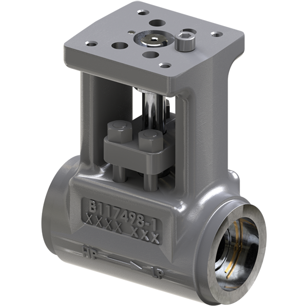
There are two identification plates on each pump. The pump rating plate gives identification and rating information. Permanent records for this pump are referenced by the Serial Number and it must, therefore, be used to order all spare and replacement parts. The last digit indicates the specific pump on orders for more than one pump. For example, if an order called for six pumps, all pumps would have the same first three sets of digits and the last digit will change to identify each of the six. (e.g. 1-21937-1-1, 1-21937-1-2, etc.) The identification number is a number which the end user of the pump requests to be put on the rating plate to identify the pump in his operation. (e.g. CWP-11 stands for Chilled Water Pump No. 11)Size Type 8X8X17 8100 Serial Number 1-21937-1-1 GPM Head (ft.) RPM 1500 200 1780 Model Number Imp. Dia. (in.) 150 14.80 Max. Field Hydrotest Pressure 262 PSI Identification No. Year C W P-1 1 2 0 0 0 MORTON GROVE, IL USA AC0687 The frame plate gives information concerning the bearings and their lubrication. The inboard and outboard bearing numbers refer to the bearing manufacturer’s numbers. Frame Inb. Brg. F-20-E4 6039 Lubrication Out. Brg. GREASE 5308 P a r t N o. AC0685
The warning and caution decals located on the pump are there for the safety of anyone involved with the installation, operation, and maintenance of the pump. PLEASE READ THE DECALS CAREFULLY. This safety alert symbol will be used in this manual and on the pump safety instruction decals to draw attention to safety related instructions. When used the safety alert symbol means ATTENTION! BECOME ALERT! YOUR SAFETY IS INVOLVED! FAILURE TO FOLLOW THE INSTRUCTIONS MAY RESULT IN A SAFETY HAZARD.
Do not operate pump at or near zero flow (closed discharge shutoff valve). Explosion could result due to large temperature rise in the fluid being pumped. Failure to follow these instructions could result in property damage, severe personal injury, or death. If pump is to be used on process fluids above 120°F, pump surface temperatures could be warm enough to cause burns. We recommended pump surfaces be insulated or appropriately guarded. Failure to follow these instructions could result in severe personal injury.
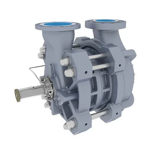
Check the pump for damage immediately upon arrival. Prompt reporting of any damage to the carrier’s agent, with notations made on the freight bill, will expedite satisfactory adjustment by the carrier. Pumps and drivers are normally shipped from the factory mounted on a baseplate. Couplings may either be completely assembled or have the coupling hubs mounted on the shafts and the connecting members removed. When the connecting members are removed, they will be packaged in a separate container and shipped with the pump or attached to the baseplate.
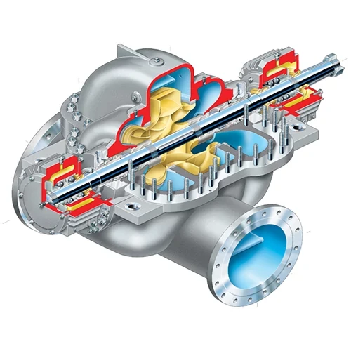
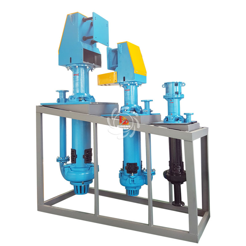
The following instructions are for the safe lifting of the Series 8100 pump. The pump unit should be unloaded and handled by lifting equally at four or more points on the baseplate. The lugs on the upper half casing are designed for lifting the upper half casing only.
Bare Pump (Model 100) WARNING: Falling Objects Hazard Eyebolts or lifting lugs, if provided, are for lifting only the components to which they are attached. Failure to follow these instructions could result in serious personal injury or death, or property damage. Using a nylon sling, chain, or wire rope, hitch around both bearing supports. Pump, Base, and Driver (Model 150) Care must be taken to size equipment for unbalanced loads which may exist if the motor is not mounted on the base at the time of lifting. Motor may or may not be mounted at the factory. Pump, base, and driver assemblies where the base length exceeds 100 inches may not be safe to lift as a complete assembly. Damage to the baseplate may occur. If the driver has been mounted on the baseplate at the factory, it is safe to lift the entire assembly. If driver has not been mounted at the factory and the overall baseplate lengths exceeds 100 inches, do not lift the entire assembly consisting of pump, base, and driver. Instead lift the pump and baseplate to its final location without the driver. Then mount the driver. Bases supplied with lifting holes: Large bases are supplied with lifting holes in the sides or the ends of the base.
Bookmark
Daniel Féau processes personal data in order to optimise communication with our sales leads, our future clients and our established clients.


This site is protected by reCAPTCHA and the Google Privacy Policy and Terms of Service apply.