


EUR
en
The Manual is for guiding the installation, operation and maintenance of 2G(2GM), 2H(2HE&2HM) and 2W(2WE&2WM) series twin screw pumps. We expect the under-mentioned instructions could be understood well and accurately followed by user. For any questions beyond this manual, please contact our technical department directly.
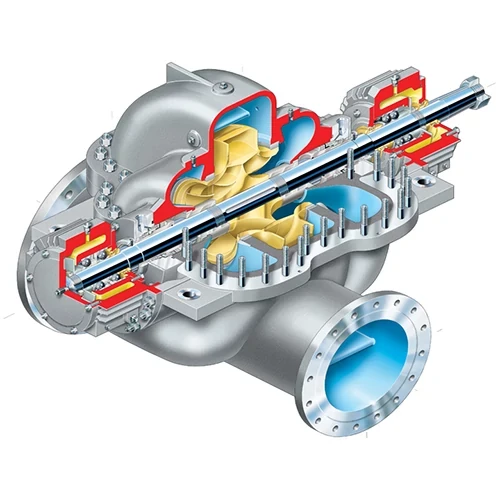
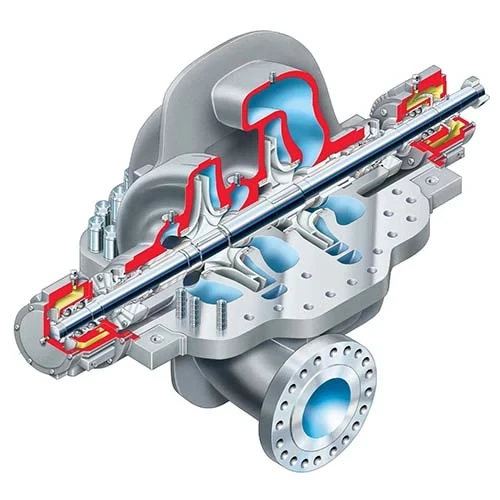
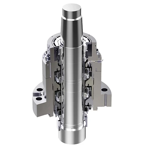
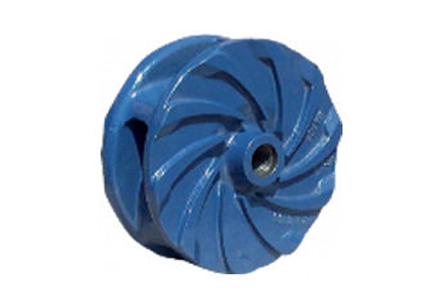
2G, 2H and 2W twin screw pump is a kind of Positive Displacement Rotary Pump, which can handle the liquid with viscosity below 3000mm/s(cSt). The pump consists of two spindles rotating in opposition. During pump’s working, a pair of screws fixed on two shafts get in mesh and form seal cavity against pump’s inner chamber. W ith rotating of two spindles, liquid in seal cavity moves axially and is transferred from inlet stably and continuously to outlet of the pump. 2G single-suction twin screw pump and 2HM,2WM double-suction twin screw pump are designed with external bearing and pump’s chamber is separated from bearing chamber by mechanical seal and framework oil seal, therefore which can transfer liquids with or without lubricity as well as liquids with high-viscosity. Material normally used for rotary ring and stationary ring of mechanical seal: TC(or ceramic) and Graphite. 2HE and 2HM twin screw pumps are designed with internal bearing. Pump’s chamber is conjunct with bearing chamber and they are mainly for transferring liquids with lubricity. Material normally used for rotary ring and stationary ring of mechanical seal: A. TC and TC. B. TC(or ceramic) and Graphite. Pump’s spindle is made up of screws and separated shaft processed by high-strength alloy steel or stainless steel for meeting the working conditions upon big power and big torque. Different metals such as Nodular Cast Iron, Nitrided Steel and Stainless Steel are selected for screws to meet the requirement to transfer different liquids. Timing gear is adopted to pass the power from driving shaft to driven shaft, which enables two spindles to rotate synchronously during their meshing, therefore low wear and big reliability. Special construction is designed at pump’s inlet to ensure uniform flow of the suctioned liquid and low pressure loss, therefore the pump has small NPSHr. And position of inlet and outlet can keep enough liquid inside the pump when it stops working, so the pump is good self-priming. Wetted parts of the pump should be selected according the chemical property of the liquid to pump: for liquids without erosion or unclean liquids, to use general steel or iron; for liquids with erosion or clean liquids, to use suitable stainless steel; for explosive or flammable liquids, such as gasoline, toluene, to use bronze; for liquids with small solids, to use high-rigidity nitrided steel; for special requirement for material, please indicate when ordering.
User is obligatory to correctly install the pump and operate safely. User must take all necessary measures to ensure the execution of safety requirement from manufacturer and industry standard for positive displacement pump (twin screw pump) 1. Select prop er carne and enough-strength steel cable when installing and stevedoring 2. When testing pipe’s pressure and flushing pipe, the pump MUST BE SEPARTED. Or the seal of pump will be damaged and incurred leakage. 3. Ensure the pipe to be swept strictly and be unblocked before first starting. 4. Fasten the plug screw in drain hole to prevent from polluting leakage 5. Select suitable coupling and guard and fix them well. 6. Ensure safety valve to work under proper capacity and pressure. 7. Make sure the pump works under right condition, otherwise, it can cause serious damage of equipment and bring danger to operator’s safety. 8. The pump can only be maintained a fter it’s stopped. 9. The pump is strictly forbidden to work without medium liquids, or the screws, bearings and mechanical seals will be damaged.
1. Within warranty period, we will p rovide repair or replace unq ualified parts at no charg e for the pump’s malfunctions ca used by workmanship. We do not take a ny liability for the damage ca used by incorrect installation or operation. 2. Our liability to the loss caused by defect m aterial or workmanship is limited to replacing or repairing damage spare parts and we do not take legal liability for the loss caused directly or indirectly by using our products or any other reasons, such as time-loss, possession-loss and safety-loss. In general, we will not take any responsibility for the damage or hurt to other equipment, machine, building, articles or personnel caused by user’s installing and using our product. 3. W arranty is invalid under following situations: a. Spare parts are dismounted, repaired or replaced without formal approval by our technical department, quality inspection department and sales department. b. Pump’s breakdown caused by contingency, operator’s careless operation or improper working condition. c. To pump the liquids not stated in contract, which might erode the pump or impair pump’s running. 4. The warranty is NOT applicable to (a) corrosion failure & abrasion failure (b) natural disaster failure (c) failure by absence of correct maintenance (d) other charge for filed-repair and replacement of spare parts.
1. The equipments should be put in a dry place without shinn ing and raining .The tim e of laying them in the open air should be not exceed one month, and our company has no responsibility for the damage caused by improper storage. 2. User should immediately check up the equipments against any loss or damage on receipt and inform shipper and our company timely for any problem. Claim for compensation must be made immediately after checking of received equipments.
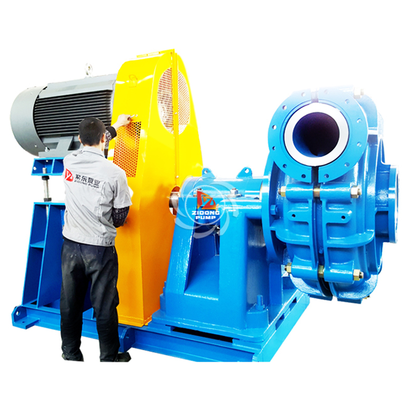
Lifting pump: infix one end of steel cable into lifting hole of casing or bearing support and infix the other end of steel cable into hoop of motor or hoop indicated on base plate.
The pump must be preserved well as follows if laid up for a long time after installation. 1. Store the pump in a dry and ventilated place, and replace seals in a year. 2. Fill pump chamber with machine oils and seal inlet and outlet to prevent the dust and impurities from the entering chamber. 3. Coat the non-painted metal surfaces with antirust. 4. Cover the pump and motor with waterproof coating.
The under-mentioned instruction is a practicable guide for user’s installing pump. Only when the following instruction is followed strictly or with other practical experience on installation can the twin screw pump work stably and reliably with long life.
The installation site should close to oil pool. Pump room should be dry and has enough space for installing and repairing. One-meter space around pump should be left for repair, better still bigger space if possible.
The pump should be installed on firm cement base whose thickness is no less than 30-50cm, subject to the size of pump set. And square hole (12x12cm) should be set ahead in cement base according to the position of stone bolt of pump set. Put the pump set on base after the cement is solidified and take the second grouting after stone bolt fixed. If the pump is installed on steel deck or other buildings, it should be installed on them directly and to be as close to primary component as possible, besides to add support to avoid deforming and vibrating. Required area for installation and position for stone bolt should follow the outline dimension supplied by our company.
Fix the pump set on base with stone bolt and check up the fastening between pump, motor and base. Check and adjust the alignment of coupling: turn coupling by hand to confirm if it rotates smoothly. Pease refer to the following demonstration as two methods to align coupling:
1. Clean the pipe before installing and get rid of iron rust, ESW and dirt inside pipe. T win screw pump is good self-priming and is easily blocked by the dirt sucked into chamber from pipe, so it is important to clean out the pipe, especially pipe at inlet before mounting the pipe with flanges of in/outlet. 2. Try to use short and straight pipe to reduce resistance and use big-curvature pipe. 3. The size of pump should be identical with that of th e pump’s in/outlet. If possible, bigger-size pipe is preferable to reduce resistance of oil-sucking. 4. Use brace to supp ort pipe and valves, preventing pump from bearing pipe’s weight. 5. NPSHa of suction pipe should b e bigger than NPSH r of pump, otherwise the pump can’t work well 6. Pressure test and performance test have been done before delivery. User should keep pump apart while doing test and flush for pipe, otherwise the pump’s seal will be damaged, causing leakage.
1. Filter. Install the filters at the suction-pipe to keep impurities from entering pump. Standard of filter screen: 20-30 mesh /inch. Filter area of filter should be 3-5 times larger than sectional area of pipe. For handling high-viscosity liquids, the filter area should be extended moderately: the standard should be 10-20 mesh/in and filter area of filter should be over 5 times larger than sectional area of pipe. The filter should be cleaned regularly and cleaning period should depend on cleanliness of medium liquids. 2. Check V alve. Check v alve or glob e valve is usually mounted with discharge pipe to prevent back flow from impacting pump after pump stalls. When several pumps are installed in parallel, only with check valve can pumps are started respectively. In case of long pipe line limited to installing field, the check valve can be mounted on the end of suction pipe to reduce resistance of oil-sucking and improve pump’s self-priming. (pump is suggested to be installed close to oil tank to shorten the pipe line) 3. Safety V alve. Both of single-suction and dou ble-suction twin screw pump are mounted with safety valve. Opening pressure is five times the rated working pressure of pump. 4. Pressure Gauge. Co mpound gauge and pressure gauge can be fixed at flanges o f inlet and outlet to monitor pump’s working condition and standard of screw hole is M14x1.5. Measuring range of pressure gauge is 1.5-2 times the rated working pressure of pump.
2HE&2WE series double-suction twin screw pump with internal bearing: timing gears and bearing to be lubricated by medium liquids, no lube oil required. 2HM&2WM series double-suction twin screw pump external bearing: timing gear and bearing near the gear box to be lubricated by 30# engine oil; bearing near bare shaft to be lubricated by Lithium Base Grease or 1# Calcium Base Grease. 2G series single-suction twin screw pump: timing gear to be lubricated by 30# engine oil; bearing to be lubricated by Lithium Base Grease or 1# Calcium Base Grease. Oil in gear box should be timely replenished to “midline” of oil level and be replaced every 3-6 months. Gear box should be cleaned out eve ry 3-6 months. Please find following interval for replacing oil in gear b ox for reference: Interval of replacing oil in gear box: Accumulated running time of new pump: 250 hours Intermittent running: every accumulated: 500-1000 hours Continuous running: every accumulated: 2000 hours Gear and bearing will be damaged when pump works with absence of oil in gear box.
Bookmark
Daniel Féau processes personal data in order to optimise communication with our sales leads, our future clients and our established clients.


This site is protected by reCAPTCHA and the Google Privacy Policy and Terms of Service apply.