


EUR
en
A centrifugal pump is a mechanical device used to transport fluids by converting rotational kinetic energy into hydrodynamic energy of fluid flow. This energy conversion is achieved through a rotating component called an impeller. The centrifugal pump works on the principle of centrifugal force. When the impeller rotates, it imparts velocity to the fluid entering at its centre (the eye of the impeller). This velocity pushes the fluid outward toward the edges of the impeller, increasing its kinetic energy. The pump casing then guides the fluid and converts much of this kinetic energy into pressure energy, enabling the fluid to flow through the delivery pipe.
A mechanical device that transfers electrical energy into hydraulic energy to move fluids (slurries, liquids, or gases) is called a pump. Centrifugal pumps follow the same principle but with some advancements. The centrifugal pump uses a rotating impeller to apply centrifugal force, thereby moving fluids. This article explores the centrifugal pump working principle, types, parts, applications, and more. Centrifugal pumps are particularly suited for low-viscosity fluids. They are widely used in water treatment, chemical processing, oil refineries, and cooling systems. Engineering students must understand these systems deeply, as they form the backbone of various mechanical operations.
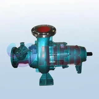
The Centrifugal Pump comprises various components, and each part plays an important role in operation. The most crucial component is the impeller, which rotates at high speed to generate centrifugal force that moves the fluid. The pump casing surrounds the impeller and is designed to guide the fluid from the suction side to the discharge side while converting velocity into pressure. Centrifugal Pump bearing supports the rotating shaft. Understanding centrifugal pump parts is crucial for design, maintenance, and troubleshooting. The main components of a Centrifugal Pump are explained below.
The impeller is the heart of the centrifugal pump. It is a rotating disc with a curved blade attached to its surface. In the working condition, the impeller spins at high speed and transmits energy to the fluid. The impeller of a centrifugal pump helps to draw fluid from the centre. It accelerates the fluid outward due to centrifugal force. The impeller increases the fluid velocity and pressure. The impeller’s size, shape, and material affect the centrifugal pump's working principle and performance. Impellers are classified into three types provided below.
The casing of a Centrifugal Pump is the outer shell that surrounds the impeller. It acts like a chamber where kinetic energy is converted into pressure energy. It helps to collect the fluid from the impeller. Casing slows down the fluid velocity to increase the pressure and directs the fluid to the outlet. A good casing ensures that pressure is not lost at any point, maintaining the efficiency. Pump casing is broadly classified into three types provided below.
The suction pipe of the Centrifugal Pump carries the fluid from he source to the pump, entering through the suction nozzle. It helps to bring the fluid to the impeller eye. The suction nozzle maintains a continuous flow for smooth operation. It must be air-tight to avoid cavitation. Correct sizing and design of the suction pipe are critical for priming.
Centrifugal Pump is a mechanical rod that connects the impeller to the electric motor. It rotates the impeller and transmits power. It helps to transfer the mechanical energy from the motor to the impeller. The shaft supports the rotating components inside the pump. The shaft of the Centrifugal Pump must be strong, durable and properly aligned.
It is used to support the shaft and allow it to spin smoothly without friction or vibration. It helps to provide support to the shaft of the Centrifugal Pump. Bearing reduces the friction and wear. It helps to maintain proper shaft alignment. If bearing is not maintained properly, then it can lead to overheating and failure of the pump. The bearing of the Centrifugal Pump is classified into two types.
These are the special types of design inside the valve which is used to convert the fluid velocity into pressure. The volute of a Centrifugal Pump is a spiral casing that widens gradually, while the diffuser is a series of stationary vanes that surround the impeller. Both are designed to improve energy efficiency and reduce turbulence.
These are the supporting structures of the pump assembly. It helios to holds the pump and motor piece of the Centrifugal Pump. Improper mounting can lead to misalignment, excessive vibration, and mechanical failure.
The efficiency of a centrifugal pump defines how effectively it converts mechanical energy into hydraulic energy. The efficiency directly affects operational costs, so calculating and improving it is crucial. There are three main types of efficiencies considered in a centrifugal pump:d mechanical efficiency, volumetric efficiency, and hydraulic efficiency. Centrifugal pump overall efficiency (ηₒ) is given by:
ηₒ = (Water Power/Shaft Power) × 100
Where:
Here,
ρ = Density of liquid (kg/m³)
g = Acceleration due to gravity (9.81 m/s²)
Q = Discharge (m³/s)
H = Total Head (m)
N = Speed (rpm)
T = Torque (Nm)
Hydraulic efficiency defines how effectively the impeller imparts energy to the fluid. It accounts for hydraulic losses due to friction, turbulence, and shock. The formula is:
ηₕ = (gHₐ / gHₜ) × 100
Where Hₐ is the actual head developed and Hₜ is the theoretical head. High-quality impeller design and smooth casing surfaces improve hydraulic efficiency.
Volumetric efficiency (ηᵥ) depends on the leakage losses that occur inside the pump due to the clearance between the impeller and casing. It is expressed as:
ηᵥ = (Qₐ / Qₜ) × 100
Where Qₐ is the actual discharge and Qₜ is the theoretical discharge. Proper sealing and regular maintenance of clearances can enhance this efficiency.
Mechanical efficiency (ηₘ) measures losses due to friction in bearings, stuffing boxes, and other moving parts. It is expressed as:
ηₘ = (Brake Power / Shaft Power) × 100
Combining all three gives the overall efficiency as:
ηₒ = ηₕ × ηᵥ × ηₘ
Centrifugal pump efficiency ranges between 50% and 90%, depending on size, design, and operational conditions. Factors such as impeller wear, air leakage, and improper speed control can reduce efficiency. Regular testing and plotting efficiency curves using centrifugal pump PPT resources help track performance.
The pump operates using the forced vortex flow principle or centrifugal action. The centrifugal pump transforms rotational energy, commonly from a motor, into the kinetic energy of the fluid. It indicates that when an external torque rotates a liquid mass, the rotating liquid pressure head rises. The rise in pressure head is proportional to the liquid's velocity at that position. The liquid moving through a rotating impeller generates a change in angular momentum, which increases the liquid's pressure. The casing of the Centrifugal Pump serves as the axial entry point for fluid, which is then captured in the impeller blades. The impeller installed on the primary mover shaft rotates, creating a suction lift at the impeller's eye. The impeller vanes impart kinetic energy to the water, which then departs and travels through a volute, where this energy is transformed to pressure (head). The hydraulic centre at the suction side and the water surface are separated by a pressure gradient measured by the pump's suction lift. This is negative pressure, and the atmospheric pressure outside the pump determines the maximum value it can reach. Check the working principle of the Centrifugal Pump step-by-step, with the role of each part explained in detail.
Before the pump starts, priming is essential. This involves filling the pump vessel and suction pipe with liquid so that no air pockets remain. Since centrifugal pumps are not self-priming, any air present would prevent proper suction. Without priming, the impeller would rotate in air, and no suction would be created.
Once the motor is turned on, it rotates the shaft connected to the impeller of the centrifugal pump. The shaft is supported by beading to reduce friction. This imparts rotational energy to the impeller. The smooth rotation helps to ensure efficient energy transfer without damage.
As the impeller starts rotating, a low-pressure region is created at the center (eye) of the impeller. Due to this pressure difference, the fluid is drawn into the pump through the suction pipe.
When fluid enters the impeller, it gets trapped between the vanes of the rotating impeller. It is operated at high speed, which helps to gain kinetic energy and is pushed outward due to centrifugal force. The impeller of a Centrifugal Pump is the key part responsible for converting mechanical energy into kinetic energy.
As the high-velocity fluid exits the Centrifugal Pump impeller, it enters the pump casing, which is usually designed as a volute or diffuser. The casing converts the kinetic energy into pressure energy by gradually expanding the flow area.
Once the fluid pressure is sufficiently increased, it is directed out of the pump through the discharge nozzle and travels through the delivery pipe to its desired destination.
When the motor is running and the impeller is spinning, the above steps repeat continuously. A balance between suction pressure and centrifugal head at the outlet is maintained, ensuring smooth and uninterrupted flow.
Before stopping the Centrifugal Pump, the delivery valve is closed to prevent backflow from the destination to the pump. Once the motor is turned off, rotation stops, and fluid flow ceases.
Each part in the Centrifugal Pump performs a different function, explained in the table provided below.
Part NameRole in Working PrincipleImpeller Converts mechanical energy into kinetic energy by rotating and pushing fluid outwardShaft Transfers rotation from the motor to the impellerMotor Provides the mechanical power needed for rotationPump Casing Converts fluid velocity into pressure and directs flowBearings Support shaft, reduce friction, and allow smooth operationSuction Pipe Brings fluid into the pump by a pressure differenceDischarge Pipe Directs high-pressure fluid to its destinationMechanical Seal Prevents leakage at the shaft exitVolute/Diffuser Enhances pressure conversion and minimizes energy losses
The highest point at which a pump can lift fluid against gravity is called the head of a pump. The head is a unit used to describe the height of a liquid column that a centrifugal pump may be able to generate as a result of the kinetic energy it imparts to the liquid. lThere are four types which are necessary while discussing pumps.
The expression is given as, h m=h s+h d+h f s+h f d + velocity head of water.
Here,
Centrifugal pumps are broadly classified based on the direction of fluid flow through the impeller. The 3 types of centrifugal pumps are radial flow, axial flow, and mixed flow pumps. Each type is designed to serve different industrial and engineering needs based on pressure and flow requirements.
In a radial flow centrifugal pump, the liquid enters teh impeller axially and exits radially. The fluid is drawn into the eye of the impeller. As the impeller spins, the fluid is pushed outward at the right angle to the shaft. Velocity increases and is converted into pressure in the casing. It is used in water supply systems, boiler feed pumps, chemical processing undsutiris and others.
An axial flow centrifugal pump pushed the fluid in the direction parallel to the shaft. The impeller acts as a propeller. It adds energy along with same axis as the fluid flow. Axial Flow centrifugal pump is ideal for low-pressure and high-volume movement. It is used in flood control, irrigation systems, cooling water circulation and others.
A mixed-flow pump combines characteristics of both radial and axial pumps. Fluid is discharged at an angle (between 0° and 90°) to the shaft. It creates both axial thrust and centrifugal force. The fluid moves in a spiral path, gaining both pressure and flow velocity. It is used in cooling towers, agricultural irrigation, cooling towers and others.
Centrifugal pumps are categorized into three main types: radial flow, axial flow, and mixed flow pumps. Radial flow pumps discharge fluid perpendicular to the shaft and are ideal for high-pressure, low-flow applications. Axial flow pumps, in contrast, move fluid parallel to the shaft, offering high flow at low pressure, suitable for flood control and circulation. Mixed flow pumps combine both principles, delivering moderate pressure and flow, perfect for industrial and agricultural use. The comparison helps aspirants to choose the right pump based on system requirements, enhancing performance and energy efficiency across various applications.
TypeFlow DirectionPressureFlow RateApplicationsRadial Flow Pump Perpendicular to shaft High Low to Medium Chemical plants, boiler feed systemsAxial Flow Pump Parallel to shaft Low Very High Irrigation, flood controlMixed Flow Pump Diagonal (angled)Moderate Moderate Water supply, cooling towers
The study of various types of centrifugal pumps is classified based on numerous factors. Below is the classification of centrifugal pumps.
There are two types of pumps under this category.
This pump has a single impeller and a maximum pressure head rise of 125 metres. Single-stage pumps have numerous advantages, including their simple construction, steady operation, high speed, lightweight, high efficiency, small volume, great flow capacity, and simple maintenance. The single impeller is intended for usage with a high flow rate and comparatively low-pressure head. The single stage pumps have their classification: Horizontal, vertical, single-, and double-suction.
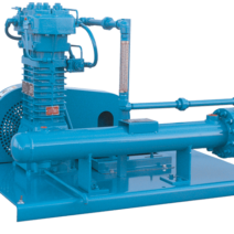
This has a first impeller that allows fluid to enter under the suction line pressure and exit at high pressure. After the fluid leaves the first stage, it enters the second, where the pressure increases even further.In the pump casing, many impellers are linked in series to form the multistage pump as shown in the figure below.
Due to their smaller impeller diameters and closer impeller clearance, these pumps are more efficient. At the end of the pump, where the fluid comes out, the pressure can be very high. Hence, when a high discharge head is required, a multistage pump is utilised.
This category also has two types of pumps.
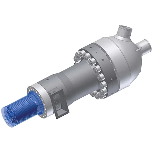
A turbine pump is essentially a centrifugal pump with a vane diffusion enclosure. The turbine pump uses a guided impeller to radially direct incoming water as shown in the schematic below. The additional component of these types of centrifugal pumps is the guide wheel, which contains several guide vanes or diffusers.
A vertical turbine pump is taken for illustration of the concept. As shown, the impeller is surrounded by diffuser blades that offer a gradually expanding channel. After passing through the blade, the liquid then flows into the housing.They are utilised in clean liquid applications where low flow, high head, adaptable operation, and compact design are necessary.
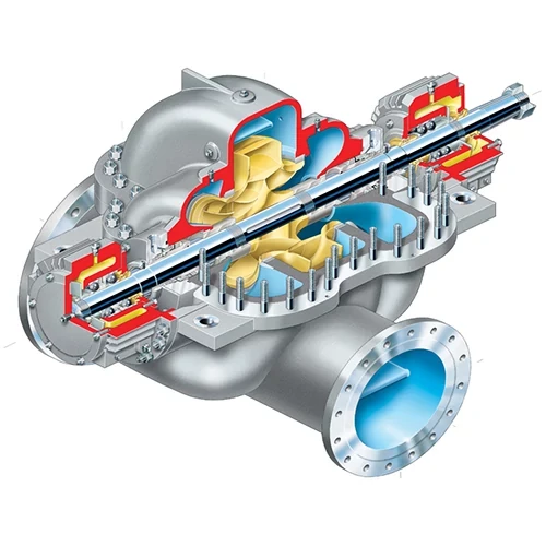
The volute casing completely encloses the impeller in a volute pump. It is constructed so that fluids moving at the same speed can enter the impeller and exit the pump. It passes the fluid that the impeller is pumping while maintaining a constant flow rate through the diffuser.
The volute pump has a low energy loss rate. The volute casing controls the flow of this highly kinetic liquid as it discharges from the impeller. This type has two classifications as shown in the above figure: Single Volute and Double Volute.
This is a common classification of pumps that are widely used. There are three types.
Now, radial pumps have an impeller that displaces fluid after turning 90 degrees to the suction. In this category, centrifugal pumps are widely used. The fluid is drawn in via the horizontal suction flange, and it is expelled via the vertical outflow flange.
It will discharge perpendicular to the shaft of the pump. When there is a flow restriction and a requirement to increase the discharge pressure, this design is frequently utilised. Radial design is therefore a high-pressure pump with a low flow rate. The majority of pumps used in the petrol and oil sectors are radial flow pumps.
The fluid flows parallel to the shaft in an axial flow pump as shown in the figure below. This process is identical to how a propellant operates. When there is a large flow rate and a negligibly low-pressure head, this pump is most useful. They are frequently used in dewatering and water circulation pumps.
With a mixed flow centrifugal pump, the fluid flow combines both axial and radial characteristics. There is a compromise between radial and axial pumps. Mixed pumps function at a much higher flow rate with an increase in the head.
The pumps under this category depend on the position of the shaft too. But there are only three types which are commonly known.
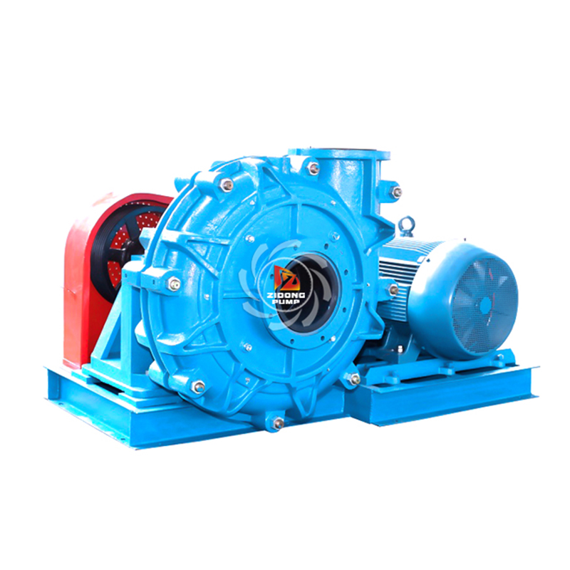
This pump functions by continually pumping fluid from a suction nozzle that is positioned in the middle of the impeller. A drive motor is used by a horizontal pump to convey liquid at a higher rate.
There is always a fluid flow and hence these pumps are environmentally friendly. The performance is good compared to other pumps.
These pumps are also called deep well turbine pumps. These centrifugal pumps have a vertical axis of flow and process the guiding vanes using revolving impellers and stages of stationary bowls. The length and rotational speed of the impeller have a significant impact on the pressure head design.
When the volume of water being pumped by a volute centrifugal pump is less, vertical pumps are employed. Vertical pumps are more expensive to replace and more difficult to install. There are several types of vertical pumps, including in-line, barrel, vertical column, submersible, and deep well pumps.
The PDF of Centrifugal Pumps is a helpful learning resource for aspirants studying fluid mechanics, hydraulics, and pump technology. Centrifugal Pump PDF comprises the working principle, construction, types, performance curves and efficiency calculations. It also includes the step-by-step derivations, solved numerical problems, and practical examples relevant to engineering applications.
A Centrifugal pump diagram visually represents the internal components and layout of the pump, making it easier to understand how it operates. A typical diagram labels the casing, impeller, suction pipe, delivery pipe, shaft, bearing, and motor. It shows the fluid entering the pump through the suction pipe into the eye of the impeller, where it gains velocity due to centrifugal force. The diagram also illustrates the transformation of velocity head into pressure head in the casing before the fluid is discharged.
We understood the different types of centrifugal pumps. There is another pump that is most commonly used along with this: the Reciprocating Pump. We have tried to state the common difference between centrifugal pumps and reciprocating pumps which are provided in the table below.
Centrifugal PumpReciprocating PumpBecause of the small number of parts, these have a simple construction These pumps have a complex construction due to a more number of partsThe pump has less head to more discharge The pump has less discharge with high headPriming is important for these pumps They are generally self-primingThe construction of the pump allows low wear and tear This pump is susceptible for wear and tearStarting torque is high Starting torque is lowAll pumps under this category have higher efficiency The reciprocating pumps have a lower efficiency compared to centrifugal pumpsHighly-viscous fluids can be handled by these pumps These pumps are restricted to low-viscous fluids as operating fluidsThe cost of maintenance is high.The overall cost of maintenance is low.
Centrifugal pumps are efficient and widely used, but they often face certain operational and mechanical issues that affect performance and longevity. These problems can occur due to improper installation, maintenance lapses, or the nature of the fluid being pumped. Understanding these issues helps operators maintain optimal performance and prevent breakdowns. Below are the common problems with centrifugal pumps, explained pointwise:
In simple terms, the process of putting liquid into the pump is called priming in centrifugal pumps. All these pumps need liquid in the casing. The impeller gets filled with vapours or air and poses difficulty in the pumping action.
Most pumps are incapable of pumping this trapped air. Thus priming removed this difficulty. But the priming is done before starting the pump as the density of the air inside it is low. Without the use of a pump, liquid can pass over the original reservoir before moving down to a lower level through a bent tube called a syphon tube.
Generally, any mechanical element that is widely used has numerous advantages. Below are some of the commonly known advantages of centrifugal pumps.
Below is a list of disadvantages of these pumps which is inevitable in any mechanical system that works.
We just read a point about cavitation posing a problem to the functioning of a centrifugal pump. Cavitation is a phenomenon that occurs when a liquid's static pressure falls below its vapour pressure, causing tiny vapour-filled cavities to form in the liquid.
These spaces, sometimes known as "bubbles" or "voids," collapse under greater pressure and might produce shock waves that could harm machinery. These shock waves are powerful while they are extremely near the collapsed bubble, but as they go away from the implosion, they quickly become weaker.
Low-pressure regions are created as a fluid accelerates past an impeller blade as it passes through a fluid. Then, when the bubbles burst, they often create shock waves in the fluid that can also harm the blades. Cavitation in pumps happens in two forms: Suction and Discharge Cavitation.
The applications of these pumps are numerous. It is easier to picture a day with these pumps in a vast majority of the industries that run countries. We have tried to capture some of the notable centrifugal pump applications.
A centrifugal pump is a mechanical device that moves fluids by converting rotational kinetic energy into hydrodynamic energy using a rotating impeller. It operates on the principle of centrifugal force, making it ideal for low-viscosity fluids in industries like oil refineries, chemical plants, and water treatment. Key components include the impeller, casing, shaft, bearings, suction, and delivery pipes. Centrifugal pumps are classified into radial, axial, and mixed flow types and can be single-stage or multistage. They offer high efficiency, simple design, and low maintenance but are prone to cavitation and limited suction lift. Applications include domestic water supply, cooling systems, and industrial fluid transfer.
Bookmark
Daniel Féau processes personal data in order to optimise communication with our sales leads, our future clients and our established clients.

This site is protected by reCAPTCHA and the Google Privacy Policy and Terms of Service apply.