


EUR
en
Series pumping uses more than one operating pump piped together to produce the design flow rate and pump head. In this regard, it is like parallel pumping – but that is where the similarities end.
In series pumping, we have one pump pumping into another. The flow rate is the same in all the series pumps. The head may be different but is normally the same is each pump. The results are a design condition of the GPM at the sum of the head of all the operating pumps.
The series curve is the sum of the pump heads of each pump at given flow rates.
When one pump is staged off, the remaining operating pump operates at the intersection of the system curve and the pump curve.
The pumps in series must have more service valves so one of the pumps may be down while others are operating. There are series pump applications out there, but it is rare that this type of design is used today.
Series pumping was used in the past because pumps with lower flow rates and higher head pressures were not readily available. They were also used in applications where the flow rate did not reduce much but the pressure drop did drop dramatically. In these cases, reducing the pressure saved the wear and tear and noise caused by severely throttled devices and constant higher pressures.
Today, we have two tools to use in these systems. The first is a much wider range of higher head pumps. The second tool is the constant use of variable speed drives. If the pressure is not required, the pump simply drops its speed, and the pump head drops as the square.
You may have run into one of these systems from decades ago. It is important to understand how they worked. It is also important to understand how you can use today’s tools to upgrade and save energy.
Sometimes you can run into a project where series pumping is causing a problem, and the series pumping was unintentional. The engineer wanted to use primary secondary pumping for freeze protection.
The plans may be inaccurate, or the installing contractor missed it in the piping. The result is two pumps in series. The main building circulating pump provides a differential pressure at the coil takeoffs. This differential will vary based on the speed of the main pump and the pressure drop in the mains but there will be some pressure difference between the supply and the return mains. The common pipe is missing.
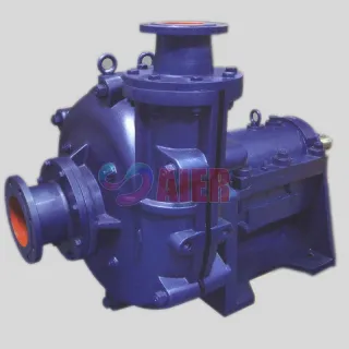
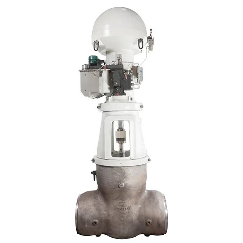
What can happen with this installation? Let’s look at an example. Assume the coil pump was designed for 150 GPM at 30 feet. The engineer selected a pipe mounted inline pump shown here. A suitable selection meeting all the basic rules of pump selection.
The issue is that the pressure differential between the supply and return will cause flow in the coil. The pump will also cause flow in the coil. The two together may cause trouble. Assume the mains have a 20 PSIG difference. You can use the Bell & Gossett System Syzer and the pump affinity laws to solve the resulting flow rate in the secondary coil loop.
The blue dot is the design flow rate and the intended operation. The red dot is the flow rate caused by unintentional series pumping. This is a significant increase in GPM. It is also running off the end of the curve.
Service contractors and owners can go nuts over this. The coil may make noise or fail due to velocity erosion. The balance valves may make a high-pitched orifice noise like a whistle. The pump may have failures every so often. The real problem is that it does not happen all the time. Most of the year the load is lower, and the main pump is at part speed. There will be an increase in flow, but it may not cause an issue. It will just waste energy.
The service contractor may miss this problem unless they read this R. L. Deppmann Monday Moring Minutes on Centrifugal Pumps – Series Pumping.
Bookmark
Daniel Féau processes personal data in order to optimise communication with our sales leads, our future clients and our established clients.


This site is protected by reCAPTCHA and the Google Privacy Policy and Terms of Service apply.