


EUR
en
P&ID symbols, also known as piping and instrumentation diagram symbols, are graphical representations of the various components that make up a process system, such as equipment, instruments, piping, valves, and others. These standardized symbols play a crucial role in helping industry professionals like engineers, technicians, and operators understand and communicate project design and process information accurately and consistently. Incorporating P&ID symbols into your work is essential to ensuring accuracy and efficiency in process management.
P&ID symbols are used to convey specific information about the components within a process system. Each symbol type has particular meanings within the context of an industry-standard notational system. The symbols fall into various categories, including p&ID equipment symbols, piping symbols, pump symbols, valve symbols, vessel symbols, instrumentation symbols, and others. These categories often have subcategories that encompass a wide range of specific symbol designs. Understanding these categories and the meanings attached to their associated symbols is essential for professionals involved in designing, operating, and maintaining process systems.
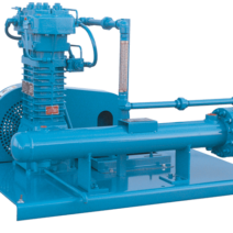
Equipment symbols in P&ID diagrams represent various pieces of hardware used in the process system. These can include compressors, conveyors, turbines, vacuum pumps, motors, heat exchangers, and other mechanical devices. Each type of equipment has its corresponding symbol that provides a visual representation of the equipment to be used within the system.
Piping P&ID symbols represent the various components involved in the transportation of fluids within a process system. These can include pipes, fittings, flanges, reducers, coupling, and other fluid transport devices. The piping symbols help engineers and technicians understand and depict the functional relationships between the piping components in a process system.
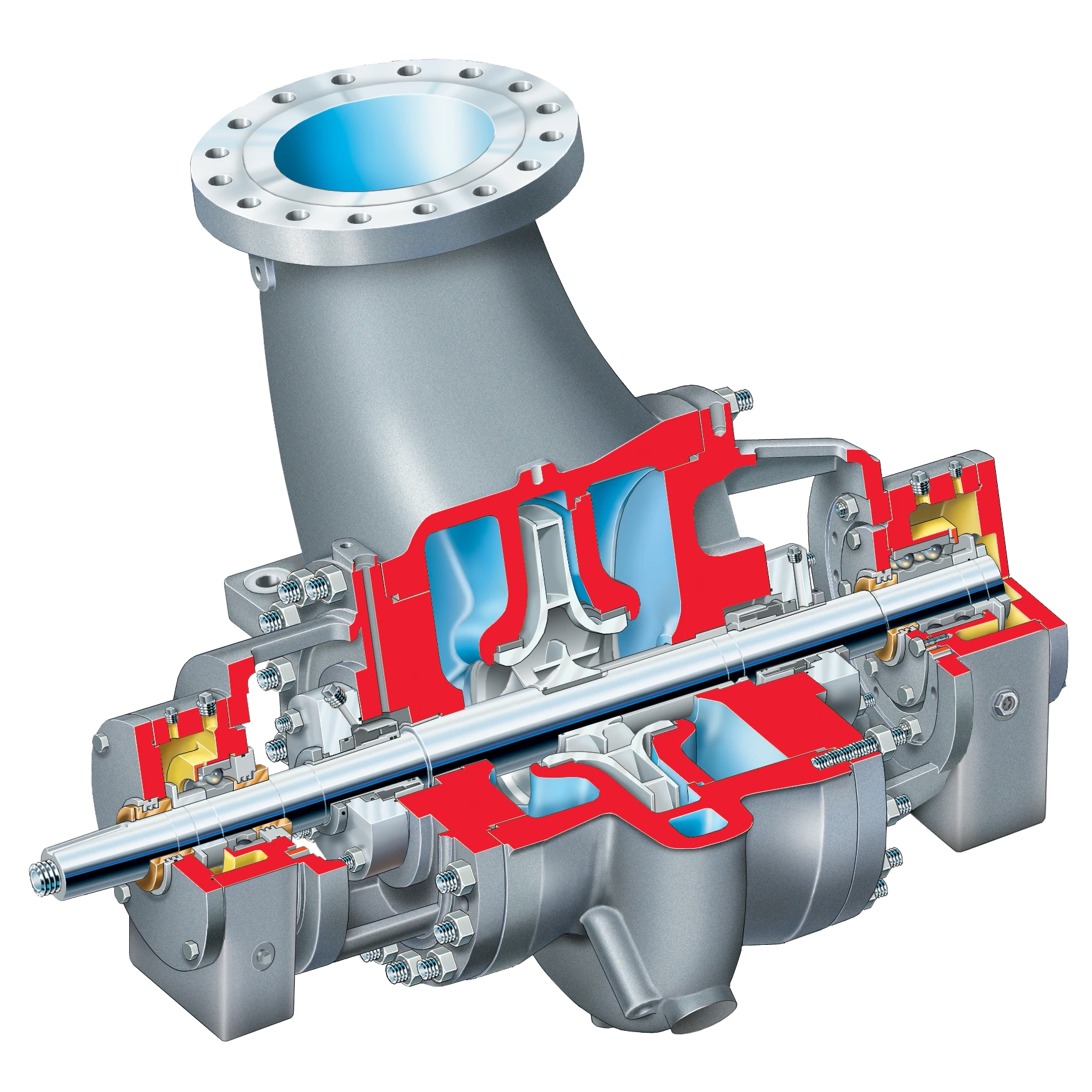
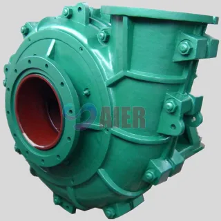
Pump symbols in P&ID diagrams are used to represent different types of pumps used in process systems, such as centrifugal pumps, gear pumps, sump pumps, vacuum pumps, and screw pumps. Understanding pump symbols is essential since they provide crucial information on the functionalities of various pumps, their connections, and the direction of fluid flow within the system.
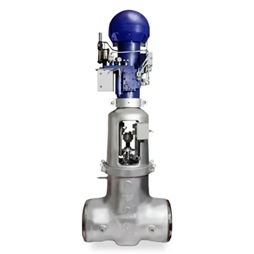
Valves are crucial components in process systems that regulate, direct, or control the flow of fluids. Valve P&ID symbols help convey information about the types and functionalities of valves in a system. Some common valve symbols include those for gate valves, check valves, globe valves, ball valves, and butterfly valves. In Europe, valve symbols may vary slightly based on regional preferences or coding conventions. These symbols are essential for depicting the precise locations, types, and functionality of valves in a process system.
Vessel symbols represent various types of containers used to store fluids in a process system. Vessel symbols include those for tanks, cylinders, columns, bags, and others. These symbols help engineers and technicians understand the capacities, shapes, and properties of different containers within a system.
Instrumentation symbols in P&ID diagrams represent devices that measure and control various parameters within a process system, such as flow, temperature, pressure, and angle. The instrumentation symbols include meters, transmitters, sensors, indicators, and other types of measurement and control devices.
Heat exchangers are devices used to transfer heat energy between different surfaces, fluids, or areas within a process system. Heat exchanger P&ID symbols represent equipment like boilers, condensers, and other heat transfer devices.
Compressor symbols in P&ID diagrams represent devices that compress gases or force air into other objects. These symbols include those for axial compressors, reciprocating compressors, rotary compressors, and other types of compressors used in process systems.
Motor symbols in P&ID diagrams represent devices that drive or power various types of equipment in process systems. Motor symbols typically include those for electric motors, generators, and other types of power sources.
Line symbols in P&ID diagrams show how signals are transmitted between equipment, instruments, and other components within a process system. These symbols indicate the type of signal being used, such as electrical, pneumatic, or data connections.
Numerous international standards and guidelines dictate the correct usage of P&ID symbols in the process industry. The American National Standards Institute (ANSI) and the International Society of Automation (ISA), among others, provide essential reference points for standardized P&ID notation. Adherence to these standards ensures effective and comprehensible communication between project teams, suppliers, and other stakeholders.
The implementation of P&ID symbols in the process industry faces a few common challenges. These include ensuring consistency and understanding among team members, keeping abreast of industry standards, and staying updated with technological advancements. Solutions like regular training, creating organizational guidelines, and making use of collaborative software tools can help address these issues.
Bookmark
Daniel Féau processes personal data in order to optimise communication with our sales leads, our future clients and our established clients.


This site is protected by reCAPTCHA and the Google Privacy Policy and Terms of Service apply.