


EUR
en
The Centrifugal Pump book is intended primarily for internal use by specialists involved in the development and manufacturing of pump components. Furthermore, the book is aimed for our future colleagues, university and engineering students, who will be able to use it as a reference and source of inspiration while studying.
Grundfos’ objective was to develop an introductory book that would provide an overview of the hydraulic components in the pump while also allowing technicians to observe how changes in construction and operation affect pump performance.
In the first chapter, we describe the centrifugal pump theory and its hydraulic components, as well as a list of Grundfos’ pump models. The second chapter explains how to read and understand pump performance curves for head, power, efficiency, and NPSH.
Chapter 3 describes how to change the pump’s performance while it is in operation in a system. Chapter 4 introduces the theoretical underpinning for energy conversion in a centrifugal pump and describes how affinity principles are used to scale pump impeller performance. In Chapter 5, we discuss the many types of losses that occur in pumps and how they effect flow, head, and power consumption.
The book’s last chapter, Chapter 6, walks us through the many test types that Grundfos conducts on both assembled pumps and pump components to guarantee that the pump performs as expected.
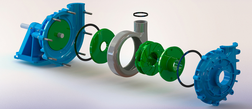
The centrifugal pump is the most widely used pump type in the world. The theory is straightforward, well-documented, and carefully tested, and the pump is durable, effective, and relatively inexpensive to manufacture. There are numerous versions based on the centrifugal pump principle that use the same fundamental hydraulic components.
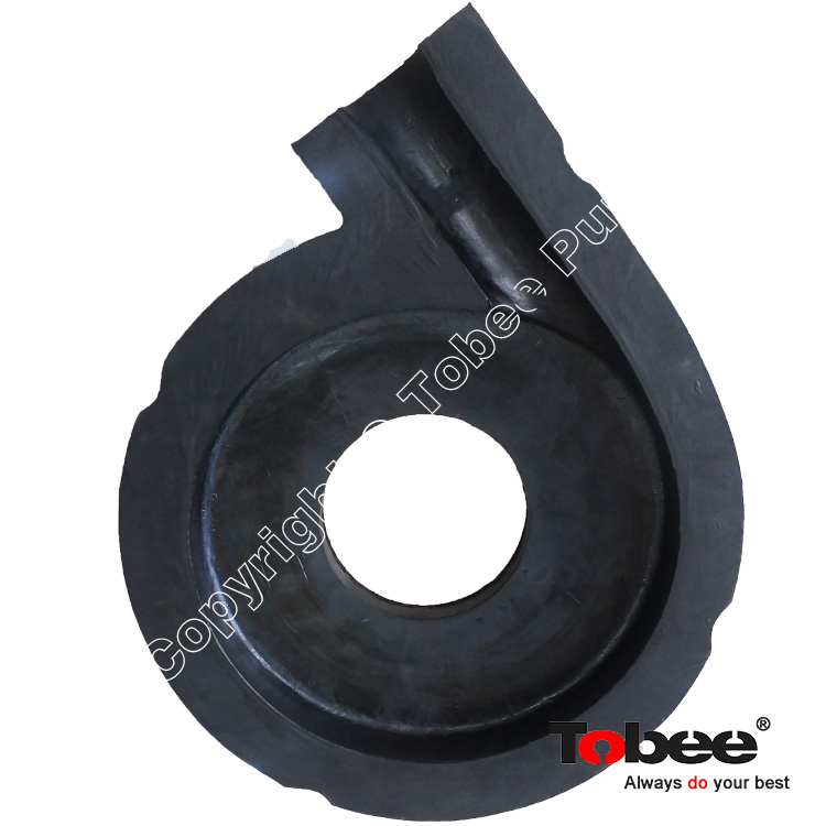
When the pump is turned on, fluid pressure rises from the pump’s inlet to its exit. This pressure differential propels the fluid across the system or facility. The centrifugal pump generates pressure by transferring mechanical energy from the motor to the fluid via the rotating impeller.
The fluid flows from the entrance to the impeller’s center and then out through its blades. The centrifugal force increases fluid velocity, and as a result, kinetic energy is transferred into pressure.
Most centrifugal pumps use similar hydraulic component concepts. The hydraulic components make contact with the fluid.
The next sections cover the components from the intake flange to the outlet flange.
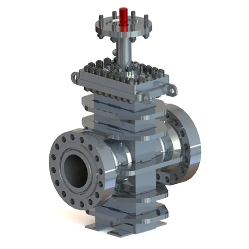
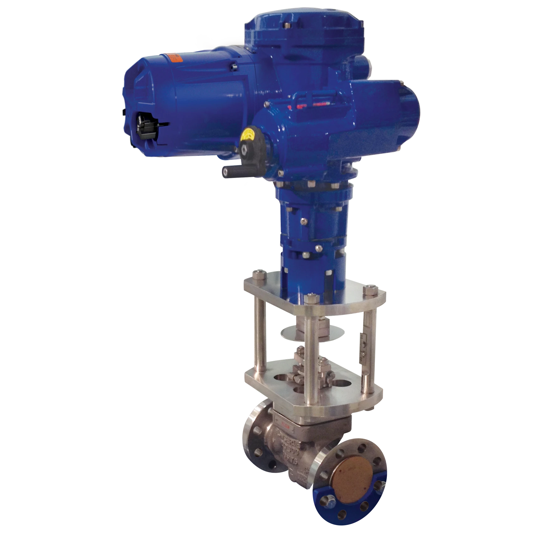
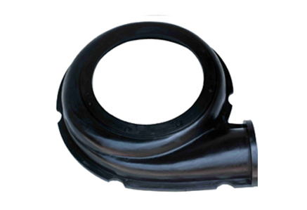
The pump is connected to the piping system via its inlet and exit flanges. The flanges are designed based on the pump use. Some pump types do not have an intake flange because the inlet is immersed in the fluid rather than positioned on a pipe. The inlet directs fluid to the impeller eye. The inlet design varies depending on the type of pump.
Inline pumps are designed to be put on a straight pipe, hence the term inline. The input part directs fluid into the impeller eye. Endsuction pumps feature a very short and straight inlet portion since the impeller eye is located in the continuation of the inlet flange.
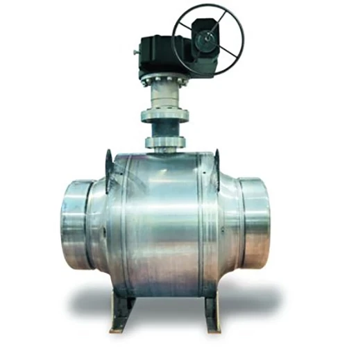
The impeller of double-suction pumps features two impeller eyes. The inlet splits in two, directing fluid from the inlet flange to both impeller eyes. This design reduces the axial force.
In submersible pumps, the motor is frequently located beneath the hydraulic components, with the inlet located in the pump’s middle section. The design eliminates hydraulic losses associated with moving the fluid along the motor. In addition, the motor is cooled by immersion in the fluid.
Bookmark
Daniel Féau processes personal data in order to optimise communication with our sales leads, our future clients and our established clients.


This site is protected by reCAPTCHA and the Google Privacy Policy and Terms of Service apply.