


EUR
en
Lets break that definition down into its components so that we can consider each one in turn:
A centrifugal pump is a mechine.
A centrifugal pump uses rotation to impart velocity to a liquid.
A centrifugal pump converts velocity into flow.
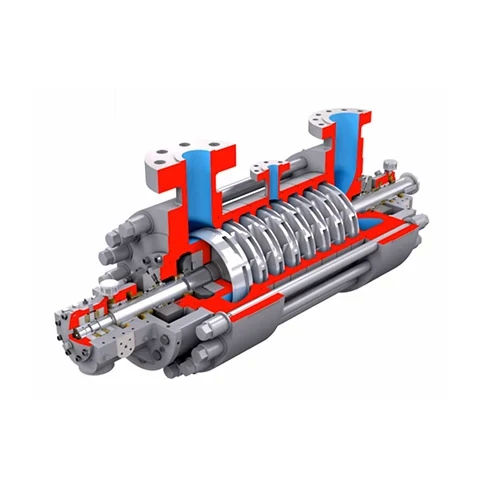
every centrifugal pump includes an set up of mechanical components which make operation from the pump possible. This mechanical set up includes the pump shaft installed on bearings, the sealing mechanism that keeps the pump from dripping excessively, structural components designed to handle stresses and loads enforced around the pump during operation, and put on surfaces that permit the pump to become repaired and came back to the original specifications.
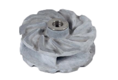
Every centrifugal pump includes an impeller. The impeller may be the hydraulic ingredient that rotates to impart velocity towards the pumped liquid.
Every centrifugal pump features a casing. The casing may be the hydraulic ingredient that captures the rate imparted through the impeller and directs the pumped liquid towards the pump discharge point.
An impeller that rotates and imparts velocity to some liquid.
A casing that captures the rate generated through the impeller and transforms that velocity right into a stable flow.
An set up of mechanical components that enables the impeller to become rotated inside the pump casing.
The impeller of a centrifugal pump is rotated rapidly to impart velocity to a pumped liquid.
If you’ve never seen a pump impeller before, visualize a boat propeller.
Each time a boat propeller is rotated it imparts velocity for the liquid around it. Since the liquid moves, that velocity forces the propeller to move forward in water.
Imagine so what can happen once the boat were moored in place, firmly enough to prevent the boat still. Next think the rate generated with the boat propeller were contained and controlled to make sure that a stream water was created you can direct that you pleased.
Basically, what we’ve just described what can be a centrifugal pump - really, an axial-flow pump resembles what we’ve just described with a significant degree.
In the centrifugal pump you own an impeller rotating rapidly and imparting velocity for the liquid inside the pump as being a boat propeller imparts velocity for the water in the lake. The casing is negligence the arrangement which takes that velocity, contains it, controls is, and transmits it along in the useful direction.
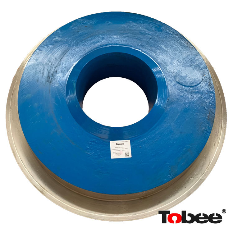
Every impeller has 1 or maybe more vanes that stretch within the center, or hub, in the impeller out for that outer diameter. Since the impeller turns, centrifugal pressure causes the liquid to move rapidly from the center of the impeller, over the vanes, then exit the impeller within the outer diameter. Consequently the pumped liquid exits the perimeter in the impeller inside a high velocity.
The centrifugal pump casing is the component of the pump that converts all of the velocity created by the rotating impeller into a controlled and stable flow and directs it out of the pump through the discharge point.
The most common type of casing is called a volute and it looks similar to a snail shell.
The impeller is positioned inside the volute. However, since you may have observed within the image above, the impeller isn't typically centered within the volute.
Rather, the impeller lies so the outer diameter from the impeller is nearest towards the volute in the point just beyond the discharge. This time in which the impeller is nearest towards the volute is known as the cutwater.
Starting with the cutwater, once we move about the impeller, the space between your volute and impeller progressively increases until we achieve the release point. This steady growth of the region round the impeller implies that pressure will build moving in the tiniest clearance towards the finest and also the growing pressure will push the liquid from the discharge point.
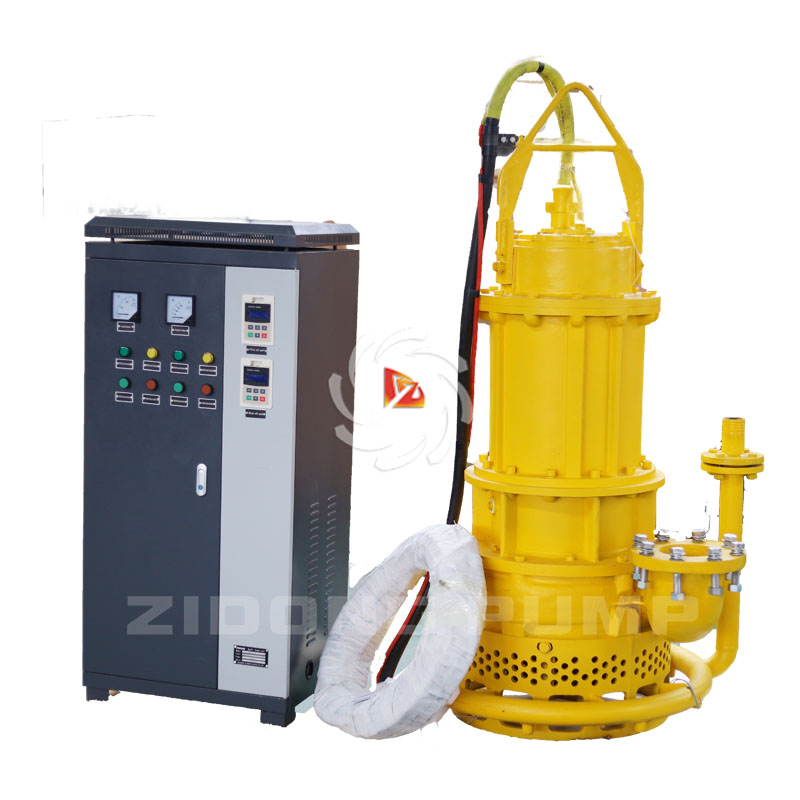
Centrifugal pumps arent much use by themselves. They should be coupled with other equipment to become helpful. The mixture of apparatus that renders a centrifugal pump operable is called a pumping unit.
At least, a centrifugal pumping unit includes a minimum of two components: a pump along with a driver.
In nearly all cases, the motive force inside a centrifugal pumping product is an motor unit. However, that is not always the situation. Pumps may also be driven by other motorists for example gas engines or perhaps steam turbines.
The most common pumping unit combines a centrifugal pump driven by an electric motor.
The picture above is of the close-coupled finish-suction pump. This is actually the simplest and many everyday sort of centrifugal pumping unit. In this kind of pumping unit the impeller really mounts around the finish from the motor shaft and also the pump casing mounts right to the face from the motor. Having a close-coupled pumping unit, the motor bearings and shaft comprise a lot of the mechanical area of the pump.
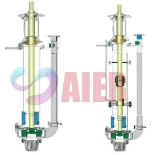
Another common pump design may be the frame-mounted finish-suction pump. Having a frame-mounted finish-suction pump, the pump does incorporate a complete mechanical set up and it is coupled to some driver, each of which are installed on a shared baseplate.
A centrifugal pump is a machine that uses rotation to impart velocity to a liquid and then converts that velocity into flow.
Every centrifugal pump consists of an impeller, a casing, and an assembly of mechanical components that make it possible for the impeller to rotate within the casing. The impeller rotates rapidly imparting velocity to a liquid. The velocity is converted into pressure and flow by the casing.
Centrifugal pumps must be combined with a driver into a centrifugal pumping unit in order to be useful. Centrifugal pumping units vary in complexity from the simplest and most common – an end-suction pump close-coupled to an electric motor – to complex custom-engineered multi-million dollar units that consist of many individual components.
Bookmark
Daniel Féau processes personal data in order to optimise communication with our sales leads, our future clients and our established clients.


This site is protected by reCAPTCHA and the Google Privacy Policy and Terms of Service apply.