


EUR
en
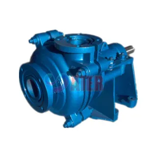
A slurry pump is a unique type of a pump which is used to handle slurry. Contrary to water pumps, slurry pumps are heavy-duty constructed and undergo more wear and tear. Technically, slurry pumps are a heavy and robust version of centrifugal pumps that have the capability of handling abrasive and tough tasks. As compared to other pumps, slurry pumps have a much simpler design and construction. Despite an elementary design, slurry pumps offer high endurance and strength under harsh conditions. These forms of pumps play a crucial role in various industries. They are fundamental to all wet processes.
In principle, it is possible to hydro transport any solid. Particle size and shape, however, may act as limiting factors based on whether they can pass through pump tubes without creating blockages. Under the broad category of slurry, there are 4 major classifications that can help you identify a suitable type of slurry pump that fulfills your demands and meets your business requirements.
Type 1: Mildly Abrasive
Type 2: Slightly Abrasive
Type 3: Significantly More Abrasive
Type 4: Highly Abrasive
If you want to move highly abrasive type 4 slurries, the ideal choice would be Oil sand pumps. The ability to handle high volumes of slurry and the enhanced withstanding capability is what gives an edge to slurry pumps. They are specifically designed to hydrotransport large-particle solids and ensure better wear performance in rough conditions.
Although centrifugal slurry pumps are widely known for their uses in oil sands, many of them have additional uses as well.
Hydrotransport — Hydrotransport pumps are used for plenty of applications because moving slurry is hydrotransport. The ideal way to use these slurry pumps is with water-based solutions. They are mostly used in industries which require dredging.
Tailings Transfer— Tailings Transfer pumps are the perfect type of pumps to transport tailings or finer abrasive materials resulting from hard rock mining, such as fragments of mud and ore, as well as related chemicals used in the mining process.
Cyclone Feed — Cyclone feed pumps, like tailings pumps, are also used in hard rock mining and are comparable to hydrotransport pumps as they are also used in dredging operations. These forms of pumps are used at all stages of scalping and separating solids by particle size.
Flotation Froth — A slurry pump can also be used for transporting froth, however the air trapped in the froth can negatively impact the pump’s performance. Even though slurry pumps are built with a sturdy construction, the air contained in the froth can damage the pump and shorten its life. But, with proper preventive measures of centrifugal pumps, you can reduce the wear and tear of the pump.
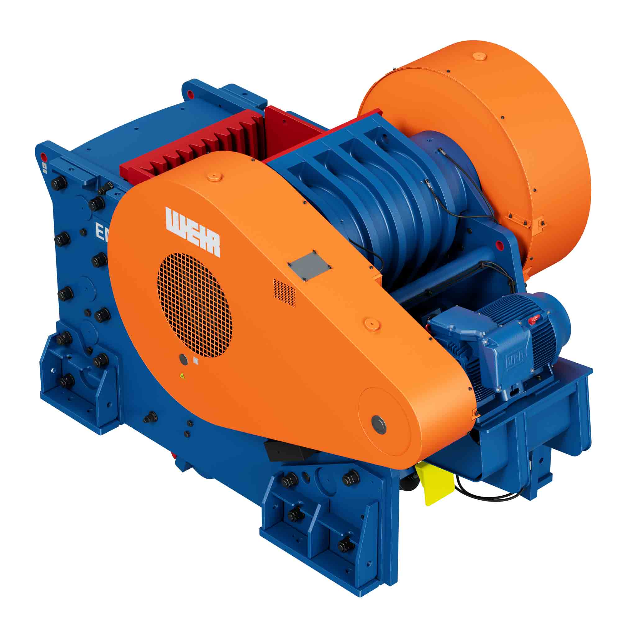
Slurry pumps have a simple and robust construction. The working principle of a slurry pump is relatively much simpler and easier to follow than other pumps.
The slurry enters the pump through the rotating impeller which imparts a circular motion. The slurry is then pushed outwards by the centrifugal force and moves between the blades of the impeller. The slurry picks up speed by the time it hits the impeller’s edge. Its high-speed energy is converted into pressure energy in the casing.
With the assistance of centrifugal force, the pumps boost the pressure of a liquid and solid particles transforming the electrical energy to kinetic energy to pump the slurry. This system allows pumping of light slurry liquids easily without much hassle and keeps it maintenance free
Easy maintenance
Low capital costs
Simple mechanism
Robust machinery
Stainless steel material to reduce wear and tear
The selection of the right pumps for specific slurries can help pump owners avoid unnecessary repairs, maintenance, related downtime and wear of the machinery. In addition to this, proper pump selection and application helps create a safer work environment for employees, ensuring a secured workplace where they can work easily without worrying about life threatening conditions in case of an improper installation. The best slurry pumps to choose for your business is the one that serves your purpose. Choosing a slurry pump depends on many factors. While selecting a slurry pump for your company, you have to analyse pump curves to identify the best option. One of the most important things to remember while selecting a slurry pump is to make sure to choose a pump that can operate as slowly as possible to reduce wear, bust fast enough to move the slurry through it efficiently without settling or clogging in the pipes. Given that these pumps have high endurance and longer wear lives, they can be used across different industries for a wide range of purposes. The most used method for selection of slurry pumps is to calculate the Total Dynamic Head for the particular application: Total Dynamic Head = Head due to friction loses + Static Head – Head due to submergence
Slurry pumps are the most preferred choice for a broad spectrum of purposes. Boosting pressure, pumping water for domestic requirements, supplying water to different areas, hot water circulation, regulating boiler water, sewage drainage and assisting fire protection systems, are among the most common applications of slurry pumps.
Pumps for grinding circuits We have a collection of specifically designed pumps that can be used for grinding circuits. For particles with size below 5mm, it is recommended to use a rubber slurry pump. If possible, mix flows that contain fine and coarse particles together for enhanced stability of the slurry.
Pumps for froth This range is specially built for froth pumping. Slurry pumps that are used for froth pumping often undergo severe abrasion and damage caused due to the air trapped in the froth, but we ensure that proper preventive measures are taken to avoid any faulty elements or decreased output efficiency.
Pumps for tailing Depending on the particle size of the slurry, both metal and rubber pumps can be used for tailing. To know more about how to choose an ideal slurry pump for your organization, you can talk to our professionals who can carry out an on-site inspection, note down all your requirements and help you in choosing the right pump for your business needs.
Pumps for pressure filter feed Choose a high head pump with variable speed control for pressure filter feed. Avoid using rubber due to the low flow head build up.
Pumps for tube press feed Metal pumps are more suitable for tube press feed as they have a high head with small flow. One slurry pumps can feed multiple tubes using a slurry distribution ring.
Vertical and horizontal slurry pumps for hydrocyclone feed Tank pumps are considered as dry installed pumps, they are a kind of vertical slurry pumps that can be effectively used for dewatering cyclones. For a sharp classification, you can use horizontal slurry pumps which are often called as dry mounted because the drive unit and the hydraulic end are located outside the sump.
Pumps for floor sumps Slurry pumps can also be used for floor sumps. Make sure to use pumps with metallic wear parts, as there is often a risk for oversized tramp material coming into floor sumps. However, if rubber must be used, put a strainer either in front of the pump or around the pump.
Pumps for wash water (sand and gravel)
Usually, vertical pumps are more preferable for wash water but you can also use horizontal pumps of a suitable range that serves your purpose.
Pumps for sand transportation
Slurry pumps are heavily used for sand transportation. The ideal choice is mostly horizontal pumps with rubber lining.
Pumps for tunnel dewatering
Since the front pumps use drainage pumps, the best choice for the initial transportation stage is vertical pumps. But, the selection of a slurry pump for tunnel dewatering depends on multiple factors such as cuttings from full-face boring, horizontal distant pumping, small tunnels, etc.
Pumps for FGD reactor feed (lime)
You can use slurry pumps with either rubber and/or metal parts. They perform extremely well in FGD reactor feeds.
Bottom ash pumping
Because of the high temperatures involved, metal slurry pumps are preferred over rubber pumps. The sturdy built of the pumps allows it to withstand strong temperatures with minimal damage and abrasion.
Fly ash pumping
There are high chances of oil contamination in the process of ash pumping. Metal slurry pumps are used over rubber for this application as they lower the risk of oil contamination. However, if rubber must be used, look for any other oil or chemicals that are not reactive with rubber.
Pumps for effluent handling
Go for metal pumps for effluent handling of the waste and recycling materials. You can use either vertical or horizontal slurry pumps, as per your needs.
Hydraulic transportation of light waste
Prefer using horizontal slurry pumps with vortex-induced flow impellers.
Pumps for soil treatment
Slurry pumps are highly efficient in soil treatment. Owing to their robust construction, they can withstand extreme temperatures and rough climate change as well.
Pumps for acid slurries
The ideal suggestion of slurry pumps for dealing with acid slurries is horizontal pumps with rubber or stainless steel. Pumps for brines Brines are usually highly abrasive and can potentially damage pumps, this is why slurry pumps are the best option to choose when working with brines. Substances like polyurethane can be used to prevent crystallization on the pump parts. Pumps for caustics Both rubber and metal slurry pumps can be used for working with caustics as it is an easy and light application.
Pumps for hydraulic backfilling Keep a close watch for any deslimed tailings. You can use metal slurry pumps with metal or rubber parts for hydraulic back filing with or without cement. Pumps for mine water (with solids) For mine water, use horizontal slurry pumps. Make sure you take preventive measures to avoid corrosion in the slurry pump as it can reduce the efficiency of the pump and damage its components.
Pumps for liquors Slurry pumps are well suitable for liquors, however, rubber is not recommended due to the risk of turpentine. Pumps for lime and caustic mud Working with lime and caustic mud involves high temperatures which can be tolerated by slurry pumps. Since the temperatures are high, it is recommended to use metal slurry pumps instead of rubber. Pumps for reject pulp (containing sand) Usually, this requires light duty pumps, but it is advised to use metal slurry pumps that can handle heavy flow and provide strong support to the slurry passing through it. Pumps for solids from debarking Use metal slurry pumps with induced flow impeller for sand and bark as they have the potential to cause heavy abrasion. Pumps for hydraulic transportation of wood chips The best option to use for hydraulic transportation of wood chips is induced flow pumps. Pumps for paper filler and coating slurry Avoid using rubber pumps as they can cause color contamination which can affect the entire production. Instead, go for metal slurry pumps that can be easily used for paper filler and coating slurry.
Slurry pumps are widely popular pumps that are used for handling robust and difficult tasks as they have sturdy construction. They can work efficiently in harsh conditions and are widely used across different industries for plenty of applications. Slurry Pumps can be used in the following industries:
Metallic & Industrial Minerals
Construction
Power & FGD
Waste and Recycling
Chemical
Mining
Pulp & Paper
When the slurry cannot be transferred from one machine to the next by gravity, one method of handling it is by means of a Wilfley slurry Pump, which is shown in Fig. 21. It is employed in most modern flotation plants for elevating and transferring all classes of material from coarse gritty slurry to fine slime. Differing considerably in design and construction from the usual type of centrifugal pump, it has the advantage that the conventional stuffing-box is replaced by a centrifugal seal which dispenses with the necessity for gland water and eliminates all wear on the shaft. This seal is so constructed that the intake chamber is open to the atmosphere. The pump can therefore have no suction and must be fed by gravity through the feed opening (35) from a box or sump designed to provide an intake head of at least 4 ft.
The pumping chamber consists of a case (1) and follower plate (3). The runner (25) is of the enclosed type with a single inlet located on the side nearer the drive, and is cast in one piece with the expeller ; the combined casting is illustrated separately in Fig. 22. It is a taper fit on the driving shaft (15) and is secured to it by a runner bolt (29). The shaft projects with very small clearance through a circular opening in the head (21) of the short cylinder (22), only a narrow annular space being left between them. When the pump is running, the slurry is prevented from leaking through this space by the expeller, which rotates just clear of a stationary die ring (26) and behaves as a centrifugal seal. Its action is due to a series of short vanes that are cast on its face, which have the effect, when rotating, of an auxiliary open runner. Thus the expeller builds up a head, depending on its diameter and speed, which counteracts the static pressure of the intake head and prevents the slurry from flowing past the die-ring and out through the annular space round the shaft, so making a stuffing-box unnecessary. Any accidental leakage from the die-ring is caught by the vanes and forced out again.
When the pump is not running, the annular opening round the shaft is sealed by the packing ring of the check valve (27). This assembly is mounted on the shaft in the short cylinder (22) and consists essentially of a spider carrying weights and a packing ring held in position by a spring. The chamber in which it revolves is open to the atmosphere through a drainage hole in the bottom. When the pump is started, the weights are moved outwards by centrifugal force, the movement being transmitted to bell cranks, which, acting against the spring, pull the packing ring off its seat on the shaft; the shaft is thus free of rubbing contact as it revolves and consequently is subjected to no wear at any point. When the pump is shut down, the check-valve operates in the reverse way and seals the annular opening so that the slurry cannot penetrate through the short cylinder (22), and damage the bearing assembly in the long cylinder (16).
The slippage seal adjustment regulates the clearance between the runner (25) and the follower plate(3) , which becomes enlarged by wear and causes a gradually increasing circulation, or “ slippage ”, of the discharged slurry back to the intake with a corresponding decrease in the efficiency and capacity of the pump. The clearance can be taken up by loosening the set-screw on the pedestal cap (28) and shifting back the whole cylinder and shaft assembly, comprising the long and short cylinders (16 and 22), the shaft (15), and the runner (25), by manipulating the nuts (11 A and B) on the threaded draw-bolt (11). The bolt is fixed to the frame and passes through a hole on a boss on the long cylinder (16), which can thus be shifted to any desired position. In practice the adjustment is made while the pump is running, the cylinder assembly being drawn back until the runner is heard to rub on the follower plate and then brought slightly forward again.
Replacement of the parts subjected to wear can be effected easily and rapidly in the Wilfley slurry Pump. The intake piping need never be touched. When a replacement is necessary, the discharge piping is raised from the case (1) by loosening two nuts in the side of the discharge keeper assembly (33) and screwing the keeper bolt (33B) upwards ; this action raises the discharge piping just clear of the joint gasket. The case (1) is released by unscrewing its two securing bolts and can then be swung out of the way by means of the crane (37), which is provided to facilitate the removal of this heavy part. The runner (25) can be released by holding the shaft (15) and turning the runner itself so as to unscrew the bolt (29) which holds it in place. The follower plate (3)has only to be lifted off its supporting pins, and the die-ring (26) can be removed after taking out two machine screws. The whole operation of dismantling these parts need only occupy a few minutes. If required, the check valve assembly can be withdrawn as a unit by taking off the short cylinder head (21) while the bearing assembly in the long cylinder (16) is of unit construction so that the barrel can be removed intact and replaced by a spare.
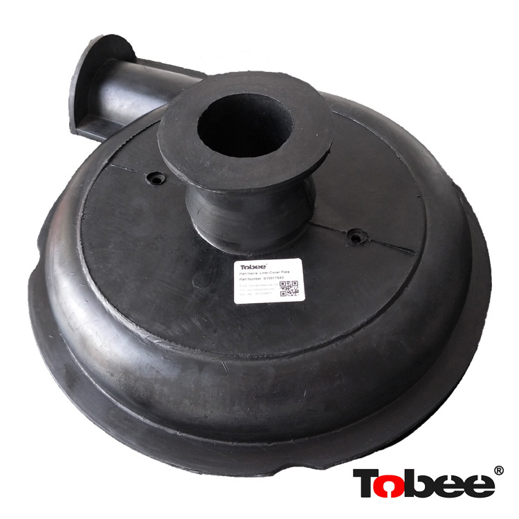
A pump that is becoming increasingly popular for handling slurry and slime is the Grit Pump made by International Combustion, Ltd. The original model is shown in section in Fig. 23A. Every part of the pump in contact with the slurry—intake piping, pumping chamber, and impeller—can, if necessary, be rubber-lined. Thus, not only gritty material but also acid liquors and corrosive slurry can be handled with minimum wear and tear.
The pumping chamber has a single inlet in the side opposite the driving shaft and is fitted with renewable end-plates of special metal, front and back. The impeller is of the full-way shrouded type with two blades. It is cast in one piece with an expeller, which is similar to that on a Wilfley pump, but is situated on the side opposite the intake opening, its purpose being to keep abrasive material away from the point where the driving shaft enters the pumping chamber. A single hexagon locking nut secures the impeller to the driving shaft so that replacements can be effected quickly and easily.
The space between each end-plate and the corresponding side of the impeller is kept clear of grit and slurry by means of a small stream of water. The latter is introduced at a pressure greater than that of the total effective head (delivery plus suction) through two ¼-in. pipes, one at each side of the impeller, at the points where the driving shaft and the inlet pipe respectively pass through the end-plates. So little abrasive material finds its way against the stream to the sides of the pumping chamber that it is normally unnecessary to line the end-plates and the outer sides of the impeller with rubber; only the intake pipe, the peripheral part of the pumping chamber, and the inside of the impeller need be protected. Should it be necessary to handle an acid liquor or a corrosive slurry—such, for instance, as one containing sea water—the end-plates and impeller are completely covered with rubber so that every part of the pump in contact with the liquid is protected.
The driving shaft runs in two ball or roller bearings placed well clear of the pump itself. A stuffing box in the casing of the pump, filled with grease packing, prevents the pressure water from leaking back along the shaft. No other lubrication is actually necessary at this point, but a grease pipe and nipple are provided, as most operators prefer to take the precaution of adding extra lubricant.
A soft rubber, made by the British Tyre and Rubber Co., Ltd., and attached to the metal surfaces by their Vulcalock Process, is used for the linings. The bond formed between the two surfaces by this method is as strong as the rubber itself.
A new model, termed the Vacseal Pump, has been recently introduced (Fig. 23B), in which the front and back covers together with the casing and impeller are rubber-covered, the end-plates being omitted. The main difference from the old model, however, lies in the design of the impeller. This is of the open type with three blades and is provided with an extension on the back consisting of vanes of larger diameter
than the pumping vanes. By these means a suction effect is exerted on the point where the driving shaft enters the pumping chamber which eliminates gland troubles and makes high-pressure sealing water unnecessary. A short gland with three rings of soft packing is provided to prevent the impeller from sucking air and to obviate leakage when the pump is not running. A single hexagon nut secures the impeller to the driving shaft as in the other model.
The inlet to the pumping chamber is short and of larger diameter than the discharge pipe in order to allow dense slurry to flow freely to the impeller. The driving shaft runs in two ball or roller bearings placed well clear of the pumping chamber and the stuffing box is readily accessible for packing purposes. The shaft is covered at this point with a sleeve of stainless steel, being thus protected against attack by corrosive liquors when the pump is stationary.
The Vacseal Grit Pump is not so foolproof to run nor so simple to repair as the Wilfley slurry Pump, but it has three advantages over the latter:
Every part liable to wear by the abrasive action of the slurry is protected by rubber, which has a longer life than metal.
Every part of the interior is protected from the action of acid or other corrosive liquids.
Whereas a Wilfley slurry Pump must be provided with an intake head of 4 ft. or more, the Grit Pump will run, if required, with a suction head up to 6 ft.
Because of their small size the ¾” and 1″ pumps are mounted on a short base and, on the standard units, wearing parts are replaced by lifting pump off its base. If desired a hinged base, as shown, can be furnished.
The pumps may be furnished with vertical flanged pulley for flat belt drive, or mule drive attachment with round rubber belts, as shown, for flat or V- belt drive.
The ¾” and 1″ pumps are ideal for use in continuous laboratory test plants. For this type of installation, where experimental work normally requires frequent flow-sheet changes, it is often convenient to have the pumps mounted on a base with casters as shown.
The 3″ and 4″ pumps are furnished as standard with a 19″ high base. If desired a higher than standard base can be furnished on the pumps. The drawing shows a 4″ pump with 36″ high base (distance between bottom of bowl and floor).
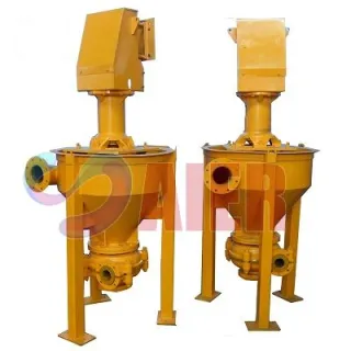
have long been leaders in the field of difficult pumping problems the pumping of sticky flotation froth, gravity concentrates, deslimed slurry, unit cell concentrates, amalgam barrel tailings, jig hutch products or any slurry containing gritty material. Any material which can be made to flow by gravity to the feed opening can be handled by these revolutionary vertical pumps.
The vertical design of Centrifugal Slurry Pumps, shown at the right, overcomes such common difficulties as stalling, caused by handling difficult slurry containing slurry or coarse material; plugging of pump, caused by use of an intake feed passage; and air locking, caused by intermittent feed or the handling of air laden slurry. Freedom from air locks plus the gravity flow principle eliminates any possibility of surging so that the discharge is at the same rate as the in-flow (up to the maximum capacity).
The feed slurry flows directly by gravity into the pump bowl and through the feed opening in top of the runner by means of the suction vortex action. Since the pump contains no intake feed passage, it is impossible to plug the pump while operating, which is an important advantage.
The new 3″ or 4″ size, shown at the right, was designed to meet a demand for larger capacity pumps for milling plants .
Other sizes include ¾”, 1″, 1½”,and 2″ pumps. These Pumps can be furnished in either motor or belt driven types.
The Vertical Centrifugal Slurry Pump consists of a vertical runner assembly with a unit bearing housing employing enclosed ball bearings. The upper bearing is of the deep grooved thrust type, while the lower bearing is of the self-aligning type. Drive is through a V-belt; sheave is keyed to upper- end of the runner shaft far above the floor with its splash and dirt. To the lower end of the tapered threaded shaft is fitted the runner.
The large cast iron pump bowl serves as the feed chamber to the runner and also supports the bearing assembly and the motor mounting, keeping it well away from possible splash and foreign matter. A hinged base can be supplied on the smaller sizes.
The wearing parts of Vertical Centrifugal Slurry Pumps are accurately designed for ease of replacement. These parts consist of Decolloy runner, Decolloy runner case and rubber follower plate. The follower plate can also be furnished in Decolloy—a corrosive and abrasive resisting alloy (high in nickel and chrome) which triples the life obtained with white iron. A replaceable shaft protecting rubber sleeve is also supplied. Special lubrication design insures trouble-free operation.
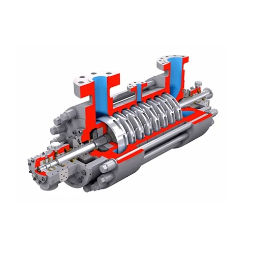
Using the conversion of rotational kinetic energy into the hydrodynamic energy of the fluid flow, centrifugal Slurry Pumps motivate fluid flow along pipelines. Pump rotation, and thus rotational energy, is typically created by the electric motor driving the Pump shaft through a V-belt drive. The fluid enters axially into the eye of the pump impeller, which by its rotation acts tangentially and radially on the fluid. The fluid is accelerated by the impeller gaining velocity and pressure, flowing radially outward into the casing, decelerating but building pressure. Being pressurized, it then exits the volute. The displaced fluid in the Pump head is replaced by atmospheric pressure and static pressure acting on the fluid in the sump, pushing it into the impeller.
The speed of the Pump is regulated by the ratio of the transmission plus, in some cases, the use of a variable frequency drive to tune the speed for a more exact duty. Care needs to be taken not to use high turn-down ratios, which result in the loss of power. Head or more specifically total dynamic head, which is the sum of static, friction and pressure heads, is used to find the speed head. Calculated water head is corrected (HR) using the d50 of the particles being pumped, the percent solids by volume. Horsepower is calculated as work done and thus includes the fluid specific gravity. Reference should always be made to the manufacturer’s curves to ensure the Pump is operating in the most efficient zone.
It should be noted that this design of Pump, unlike a self-priming positive displacement Pump, does not actually suck the fluid into the casing. As discussed above, the fluid flows into the Pump based on atmospheric pressure and the height of fluid in the vessel (14.5 psi or 33.5ft.hd. [10mhd] + the height to water level in the Sump).
Other factors affect the performance of the Pump, most important of which is the Net Positive Suction Head (NPSH), which is not only an equipment issue but a system issue. NPSHA is a measure of how close to vapor pressure the fluid becomes. NPSHR is head value on the suction side that is required to keep the fluid from cavitating. Heated solutions are particularly prone. Significant damage can occur to the impeller and bearings when a Pump is cavitating.
The reverse function of the centrifugal Pump is as a water turbine converting potential energy of water pressure into mechanical rotational energy. Examples of this are in tailings disposal down long inclines to ponds. Special builds are required.
Lining materials vary and are typically selected based on the materials to be handled and any chemistry present. Most sand sized materials
Bookmark
Daniel Féau processes personal data in order to optimise communication with our sales leads, our future clients and our established clients.


This site is protected by reCAPTCHA and the Google Privacy Policy and Terms of Service apply.