


EUR
en
To avoid expensive repairs and downtime, take a minute and verify that your impeller is rotating in the right direction. Problems you might see if your impeller is installed backwards:
Pump does not deliver water
Insufficient flow delivered
Insufficient pressure developed
Pump requires excessive power
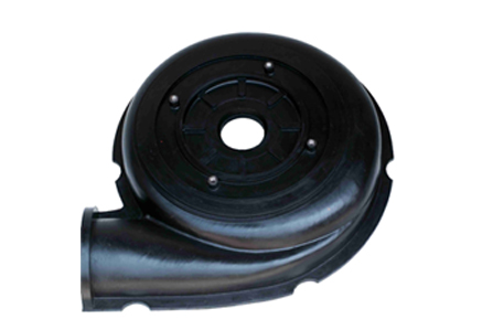
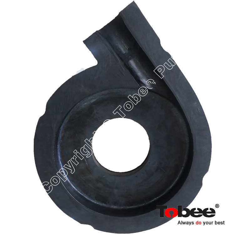
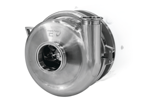
The impeller in this picture was installed backwards. When looking at the impeller from the back of the pump, make sure the blades are backhanding the water and not cupping it.
Operation of the pump with the impeller rotating in the wrong direction will result in greatly reduced performance and increased wear. Check the impeller assembly to make sure the vanes curve backward from the hub out in direction of rotation as shown in the figure below. If incorrect, the impeller is installed backwards and must be reversed on the shaft.
Warning: Before performing maintenance, disconnect the power source and take any necessary precautions to assure that power to the pump will not be engaged while work is being done.
Note: Ridding the shaft of paint with paint remover, cleaning and sanding the shaft with an emery cloth, and oiling the shaft may assist in impeller removal and installation.
Remove the nuts from the bolts on the casing back door (6-18 nuts depending on pump size).
If water-lubricated bearings are used, no loosening of set screws on the bearing eccentric collar is necessary prior to back door removal. This type of bearing is assembled to slide over the shaft. However, if sealed bearings are used, loosening of the set screws on the bearing eccentric collar is necessary to allow the bearing to slide over the shaft. (See note below.)
Remove the casing back door. Mark the casing and casing back door so reassembly will be to the same bolt pattern. Tapping the back door around the bolts may be necessary for removal due to adhesive glue or gasket holding the back door to the casing.
Loosen the impeller hub set screws.
Slide the impeller off of the shaft.
Remove key stock from shaft and inspect for wear or damage.
Clean the impeller hub and shaft to assure both surfaces are clean, smooth, and free of paint, burrs, sharp gouges, etc.
Place key stock in the shaft keyway
Apply anti-seize lubricant to shaft and key.
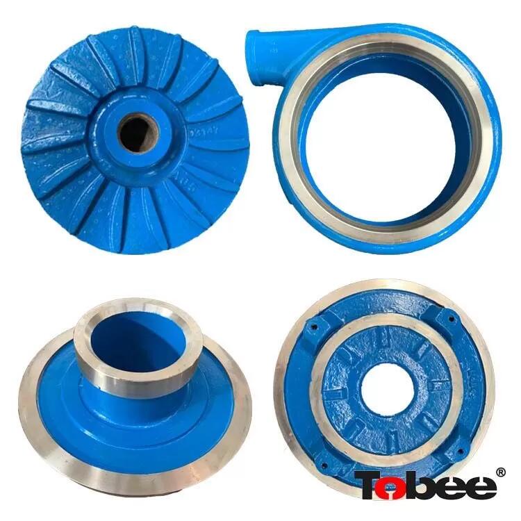
Slide impeller onto the shaft and over the keyway. Check the impeller for correct vane curvature as discussed above.
Center the impeller in the volute. The impeller is set equally spaced between front and back cases of pump to allow it to spin free. The tolerance between inside the pump case and impeller is generally about 1/8".
Block the impeller to prevent rotation.
Tighten the impeller set screws which hold the impeller to the shaft. Do not lubricate the set screws.
Slide the back door and bearing over the shaft. Align the back door to the proper bolt holes and install two or three nuts. Turn the shaft and check the
If the impeller is rubbing the casing, remove back door, adjust the impeller, reassemble and recheck for proper clearances.
Once the impeller is centered properly, slide the back door a few inches away from the casing and spread gasket cement around the back door where contact is made with the casing. This will prevent leakage from the pump and will improve overall performance.
Bolt the back door to the casing.
If water lubricated bearings are used, no set screw adjustment is needed. Tighten the eccentric lock collar to the bearing by use of a punch and then tightened to the shaft by set screws.
Remove any impeller blocking devices. Turn the shaft to check alignment; shaft should turn freely by hand. If binding of the shaft occurs, adjust bearings and recheck alignment.
Bookmark
Daniel Féau processes personal data in order to optimise communication with our sales leads, our future clients and our established clients.


This site is protected by reCAPTCHA and the Google Privacy Policy and Terms of Service apply.