


EUR
en
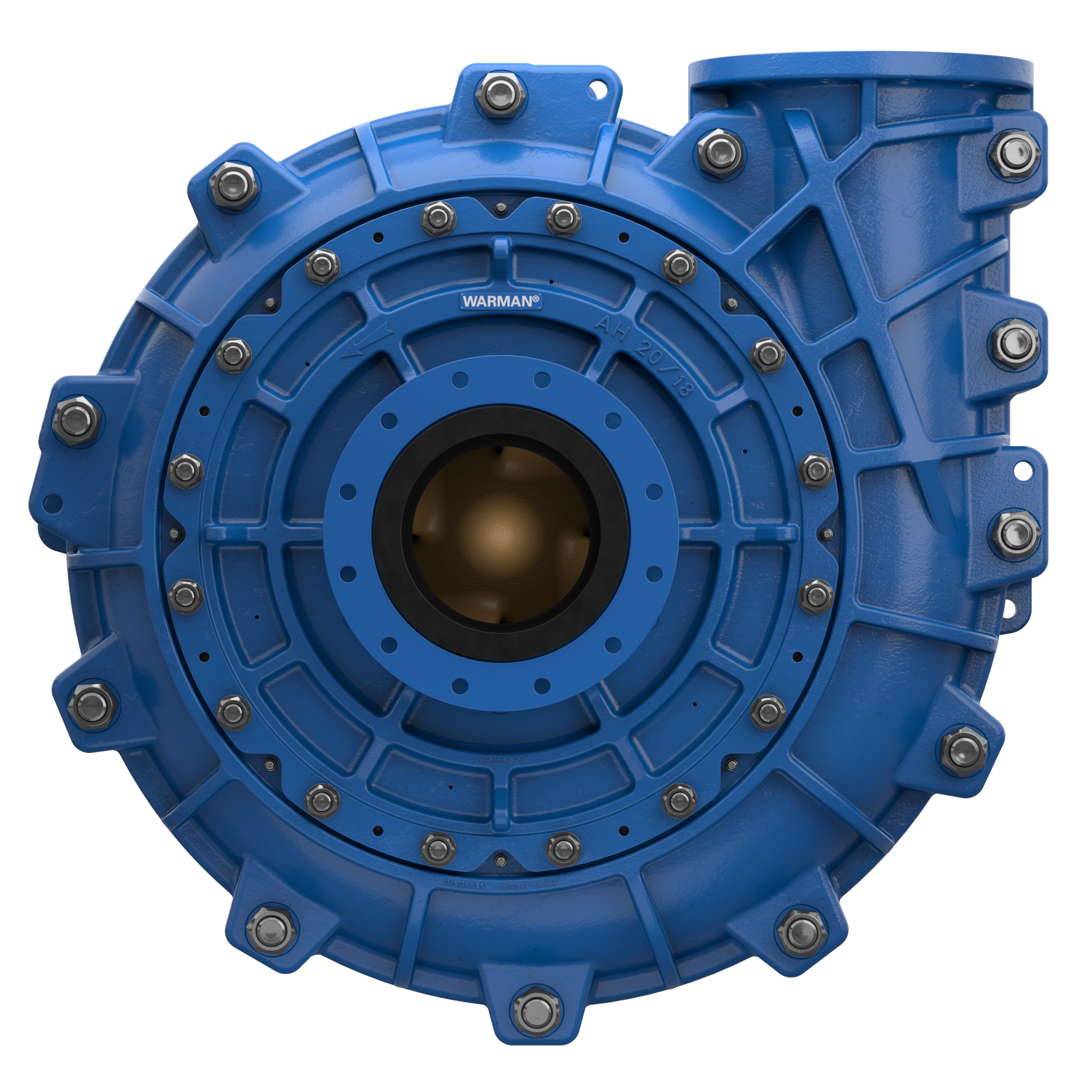
Centrifugal slurry pumps are commonly employed to convey slurries and ores due to the abrasive nature of the transported media, which often contains particles such as sand and mineral ores. The constant friction and collision of these particles with flow components lead to premature wear, particularly affecting the impeller and pump casing, which may eventually separate and compromise the operational reliability and safety of the system. To improve the overall durability and performance of slurry pumps, it is crucial to investigate the mechanisms of particle-induced wear on flow components, identify areas most susceptible to wear, and provide theoretical recommendations to enhance the wear resistance of the impeller.
Extensive research has been conducted to explore the performance and longevity of centrifugal slurry pump components. Wang et al. utilized an advanced CFD-DEM model to evaluate hydraulic performance and wall erosion under varying particle size distributions (PSDs), supported by experiments involving clear water and jet erosion. Their findings indicate that an increase in PSD intensifies erosion, underscoring the need to optimize flow structures to improve resistance and minimize particle accumulation on the impeller. Tarodiya and Gandhi examined impeller mass loss and investigated how two-phase flow, particle size, and rotational speed influence wear. Shrestha et al. applied the Finnie erosion model to assess the impact of river sediment shape and concentration on turbine wear, identifying the most vulnerable areas. Tao et al. utilized numerical models to analyze the relationship between the blade thickness and the semi-open impeller wear, observing that an increased blade thickness escalates wear on the blade’s suction surface while reducing wear on the pressure surface. Through three-dimensional numerical analysis, Mendi et al. investigated how particles under high sediment conditions induce flow instability and erosion, revealing that higher particle concentrations lead to larger amplitude fluctuations and that larger particles significantly elevate erosion rates, mainly via impact and sliding friction mechanisms. Furthermore, Wang et al. used experimental and computational methods to show that optimal coating thickness reduces outlet pressure fluctuations, radial force variations, and impeller wear under sediment-laden conditions.
Erosion modeling in pumps has garnered significant attention from researchers employing CFD techniques to simulate particle–fluid co-flow and to understand particle-induced wall erosion mechanisms. Both the Eulerian–Eulerian and Eulerian–Lagrangian frameworks have been applied extensively in this context. The Eulerian–Eulerian approach, which treats both solid and liquid phases as continuous media, is suitable for scenarios with small particles and high solid volume fractions. In a gas–liquid two-phase flow, wear and erosion issues also arise; however, the wear mechanisms differ from those in solid–phase flows, with erosion in gas–liquid phases primarily caused by impingement and cavitation. Hu et al. examined the effects of rotor–stator axial spacing on a gas–liquid–solid multiphase rotodynamic pump, finding that increased spacing reduces efficiency, intensifies vorticity, and alters pressure fluctuation patterns. Li et al. found that increasing the liquid flow rate and inlet gas void fraction in a gas–liquid multiphase rotodynamic pump reduces pressurization, with bubble sizes following a normal distribution and influenced by vortices. Liang et al. found that increased rotor-stator interactions and flow separations in a pump-turbine’s vaneless space intensify pressure fluctuations and energy loss, particularly under nonoptimal conditions. Li et al. found that interactions between vorticity sheets and diffuser blades, along with vortex shedding at the trailing edge, cause significant pressure fluctuations and turbulence in a centrifugal pump with a vaned diffuser. Wang et al. demonstrated that HT200 impellers exhibit superior corrosion resistance but noted that increased particle concentration and size markedly exacerbate wear, especially along the midsection and trailing edges of the blades. Peng et al. assessed the effect of flow rate on hydraulic efficiency using the Eulerian–Eulerian method, finding that a rising particle concentration results in a reduction in both pump head and efficiency.
Similarly, Nicolo employed the Eulerian–Eulerian method to analyze pump performance across varying particle sizes (0.1 mm to 0.5 mm) and solid volume fractions (20–30%), revealing consistent head loss with larger particles and more pronounced variability with smaller particles. However, the Eulerian–Eulerian approach sometimes lacks accuracy due to its inability to account for specific solid phase characteristics, necessitating the Eulerian–Lagrangian approach under certain conditions. The Eulerian–Lagrangian method, where the solid phase is treated as discrete entities governed by Newton’s second law and the liquid phase by the Navier–Stokes equations, provides higher fidelity in simulating sediment-laden flows. Using this approach, Pan et al. numerically simulated liquid–solid flow in reversible pump-turbines, identifying the runner as the most erosion-prone component, primarily on the mid-pressure side, with erosion rates higher in turbine mode. Lai et al. combined the Finnie wear model with the Eulerian–Lagrangian coupling model, finding that impellers experience higher wear compared to diffusers, with the shroud sustaining the most wear, while the blades and hub exhibit minimal wear. Additionally, Wang et al. emphasized that erosion rates in hydraulic systems exposed to cavitation and sediment are significantly impacted by flow velocity, with rates increasing proportionally to the velocity raised to the power of 3 to 4. This exponential relationship highlights the exacerbating effect of high velocities on wear in sediment-laden flows, accelerating degradation in critical components such as pump impellers, turbines, and blades, thus necessitating more frequent maintenance. Dong et al. underscored that erosion rates increase significantly with rising velocity, adhering to a power law of 3.4. This heightened velocity amplifies sediment impact energy, leading to intensified wear, particularly on turbine surfaces, thus making erosion-resistant design considerations critically important.
While prior research has primarily focused on pump wear through experimental and modeling approaches, limited attention has been given to understanding erosion and wear processes specifically arising from particle–wall collisions. The CFD-DEM approach is thus critical for studying pump wear in detail, considering contact forces and particle fragmentation. This method provides comprehensive insights into fluid flow fields and particle motion, enabling a more accurate characterization of particle–fluid interactions. Accurate wear predictions for flow components in particle-laden flows rely heavily on understanding particle movement and fluid flow characteristics within the pump. This study aims to establish a comprehensive CFD-DEM model for examining particle–fluid co-flow, developed in C++ on the Eulerian–Lagrangian framework. The E/CRC wear model, integrated via EDEM, enables precise simulation of erosion on flow-passing components in centrifugal slurry pumps, offering theoretical recommendations for enhancing impeller wear resistance by optimizing blade design parameters.
In this section, a comprehensive overview is presented of fluid control equations, particle control equations, and wear models, offering detailed insights into these topics.
Historically, numerical simulations frequently employed a one-way coupling approach that helped to reduce computational complexity and requirements. Nevertheless, this approach overlooked the interaction forces between particles and fluids. Thus, in pursuit of more precise results, a two-way coupling method (allowing for mutual interaction between particles and fluids) has been adopted. Furthermore, the following fluid continuity and momentum equations can be derived by considering the presence of regionally high particle volume fractions throughout the simulation:
where the volume fraction of the fluid is denoted by α f, the fluid dynamic viscosity is denoted by μ f, the turbulent viscosity is denoted by μ t, the total force experienced by particle i in the calculated unit is denoted by f, the number of particles in the calculated unit is denoted by m, and the calculated unit volume is denoted by V.
Considering that forces affect particle motion states, which in turn affect component wear patterns, is critical for researching erosion in particle–fluid co-flow. This study employs the Euler–Lagrange method, which considers particles as distinct entities and solves them using EDEM. The translation and rotation motions of particles adhere to Newton’s second law. The individual particle’s motion equation is described by a first-order ordinary differential equation:
where **F**drag represents the drag force; **F**bg represents the combined force of gravity and buoyancy; **F**Loth represents the Loth lift force on the particle; **F**pg represents the pressure gradient force on the particle; **F**vm represents the additional mass force on the particle; **F**c represents the inter-particle and particle–wall contact forces; I s represents the moment of inertia of the particle; **T**c and **T**f are the particle contact torque and the torque generated by the fluid phase, respectively; d**v**s/d t represents the translational acceleration of the particle; m s represents the mass of the particle; and d s represents the particle mass path.
Gravity and drag forces are the primary factors that have the greatest influence on particle motion. In order to calculate the drag force, this study employs the Di Felice drag force model. Currently, the Saffman lift and Magnus lift are commonly employed as the primary sources of lift, which originate from gas–solid two-phase flow and have a tendency to amplify the lifting force on particles in particle–fluid co-flow simulations. Predictions about the distribution of particle volume fractions are improved and experimental data are better matched by using the Loth lift force model in this investigation. When the ratio of fluid density to particle density exceeds 0.1, it becomes imperative to account for the impact of virtual mass force and pressure gradient force on particle motion. The objective of this study is to examine the correlation between fluid density and particle density. It has been observed that the particle density exceeds the threshold of 0.1, with a value of 0.38. Therefore, the coupling interface is designed to incorporate both the virtual mass force and pressure gradient forces. The Hertz–Mindlin (no slip) model is the basis for the contact force model used in EDEM for particle–particle and particle–wall interactions. Two separate parts of the model are computed using the softball model.
Research has focused on developing mathematical models to describe wear rates and associated challenges. The wear rate (ER) is a measure of the amount of material that is lost from the outer wall surface of a flow-passing component per unit area in a given period. The computation approach entails aggregating the harm inflicted by every particle–wall collision.
Several mathematical formulas have been created to forecast wear following Finnie’s inquiry on the topic. The E/CRC model, created by Tulsa University’s Wear/Corrosion Research Center, is used in this study. The mathematical representation of this model is as follows, and it is used to forecast the erosion conditions of elbows:
where F s is another variable, BH is the wall material’s Brinell hardness, and wear rate (ER) is a unitless metric. When it comes to sharp particles, the shape coefficient F s is 1. Semicircular particles have an F s value of 0.53, compared to 0.2 for spherical particles.
Under specific material and operating conditions, the wear rate on the outer surface of flow components is primarily determined by the value of F(α), as shown in Equation (7). The relationship between the function F(α) and the variable α, which represents the particle impact angle, is illustrated in By examining the graph, we observe that as the value of α increases, the function F(α) initially exhibits a sharp rise, followed by a gradual decline. At around 50°, F(α) reaches its maximum value, indicating the highest wear rate. reflects the trend of wear rate variation under different particle impact angles, demonstrating that wear is most severe at this specific angle.
This section checks the CFD-DEM method’s correctness for pump applications. It encompasses activities such as dividing the mesh, configuring simulation parameters, and verifying the mesh’s independence from the calculation time.
Shi et al. used PIV technology to quantify the velocity of the pressure surface of a centrifugal pumps blade while transporting a mixture of glass and water. This study will construct a volute and impeller water model based on the geometric characteristics found in the literature. The model is divided into smaller sections, as seen in The turbulence model follows the Re-Normalization Group (RNG) k-ε model with the mass flow intake, free flow, the impeller speed of 900 r/min, the simulated impeller spinning 20 times, the particles start to form at 0.01 s, and the volume fraction is 5%. The calculation formula of specific speed is as follows:
where n is the impeller speed, Q is the mass flow rate of the liquid, and H is the head of the pump. The specific speed of this pump model is determined to be 117. Specifically, there is an interface between the inlet extension in a and the impeller inlet in b, another interface between the impeller outlet in b and the volute inlet in c, and a final interface between the volute outlet in c and the outlet extension inlet in d. The specifics of the fundamental parameter calibration of EDEM and Fluent are provided in The arrangement of the data points on the pressure side is dictated by the ratio of the distance between the front edge of the pressure side and the length of the blade (Z/L).
The comparison between the experimental and simulation results primarily focuses on the velocity distributions of fluid and particles along the blade pressure surface, as shown in a,b. The figures demonstrate a strong correlation between the simulation and experimental data. Specifically, the red markers (representing the simulation) and the black squares (representing the experimental results) follow the same general trajectory, indicating that the simulation accurately replicates the velocity profiles observed in the experiment. Both fluid and particle velocities show a similar trend, progressively increasing from the inlet to the outlet of the blade. The close agreement in overall velocity patterns and magnitudes highlights the strong consistency between the two, confirming that the CFD-DEM simulation effectively captures the particle–fluid interactions and flow behavior within the pump. Although minor localized differences exist, the strong correlation between the two data sets validates the reliability of the simulation model in replicating multiphase flow dynamics.
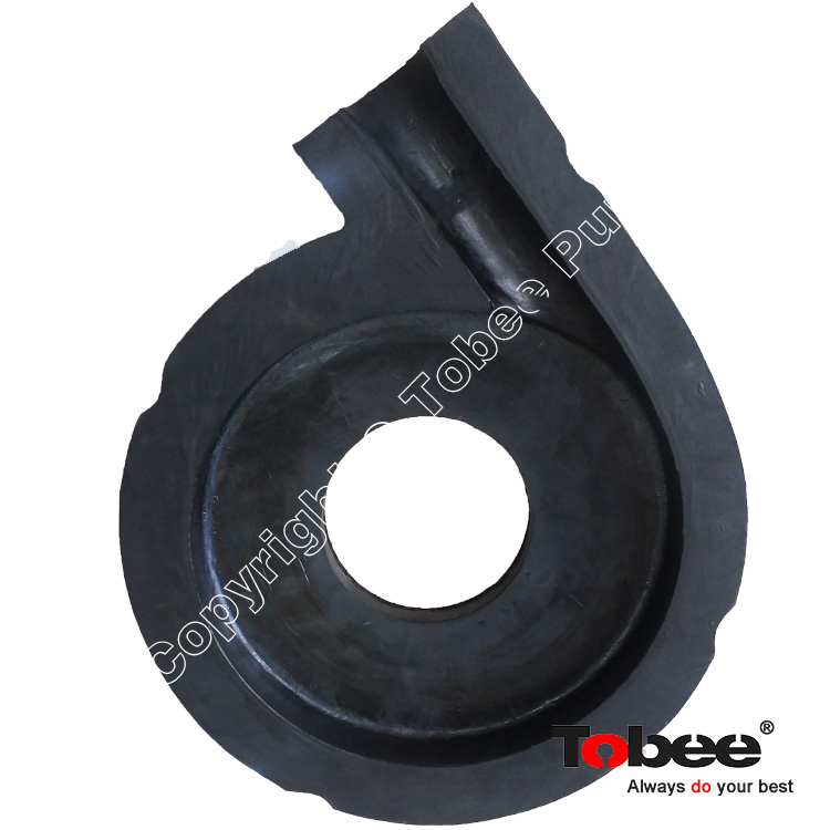
Slurry pumps are commonly employed for the conveyance of ores. The selected research topic for this study is the 100SHL4147 centrifugal slurry pump. displays the precise geometric specifications of the pump. A three-dimensional water model of the centrifugal slurry pump is generated using NX 12.0 software, as depicted in The pump comprises four primary elements: impeller, volute casing, and enlarged sections for the inlet and outlet. The expanded sections have the purpose of facilitating the uniform advancement of incoming particles and fluid at the impeller intake, while simultaneously inhibiting the occurrence of reverse flow at the exit. The length of the expanded sections is determined to be four times the diameter of the inlet/outlet pipes. The slurry pump impeller, volute, inlet, and outlet are divided into structured grids using ICEM-CFD, as seen in
The model in this study was based on frozen rotor simulations, which were conducted prior to grid independence verification and transient calculations. The CFD simulations employed the RNG k-ε turbulence model, with EDEM-UDF coupling to handle interactions between the liquid and particle phases, using the Euler–Lagrange approach. Particles were introduced into the system after 0.01 s, with the flow rate set to the design condition. The simulation focused on the 100SHL4147 centrifugal slurry pump, with a design flow rate of 18 m 3/h, a head of 8 m, and a rotational speed of 1500 rpm. A computational grid was established, and mesh independence was verified to ensure the accuracy of the results. The simulated operating point was based on the pump’s design flow condition, with an inlet velocity of 1.656 m/s. The inlet is configured with a turbulence intensity of 5% and the hydraulic diameter is adjusted to coincide with the inlet diameter of the suction chamber. The discharge port is designed to permit unrestricted flow. The EDEM particle factory starts producing particles at 0.01 s and is located at the pump inlet. Particles are discharged as they reach the pump’s exit. In order to determine the wall wear rate of flow-passing components, the E/CRC wear model is used, while the Hertz–Mindlin (no slip) model is utilized for particle–particle and particle–wall interactions. Both EDEM and Fluent have their calculation time steps set to 1 × 10⁻⁵ s and 1 × 10⁻⁴ s, respectively. The details of the basic parameter calibration of EDEM and Fluent are shown in
This work examines the impact of particle volume fraction on the computation. To ensure accuracy, the grid volume of the fluid domain must be 10 times larger than the volume of the particles. The water section of the 100SHL4147 centrifugal slurry pump is distinguished by a relatively low-density mesh partition. To assure the correctness of the chosen grid for calculating clean water and particle–fluid co-flow conditions, as well as to save computer resource, simulation were performed to replicate clear water conditions using five sets of structural grids with the following varying numbers: 308,947, 208,528, 161,530, 92,905, and 65,524. These grids are constructed for the 100SHL4147 centrifugal slurry pump. An appropriate set of grids was chosen by monitoring the variations in the head and efficiency of the slurry pump. displays the head of the 100SHL4147 centrifugal slurry pump, whereas shows its efficiency. Both measurements were taken using five different grid numbers. Observations suggest that the slurry pump maintains a consistent head fluctuation of 1% and efficiency fluctuation of 2%, regardless of variations in the number of mesh divisions. The performance characteristics exhibit a negligible fluctuation of less than 1% upon reaching a mesh count of 161,530, therefore making it the chosen option.
The main objective of this study is to investigate the wear and tear that occurs in the 100SHL4147 centrifugal slurry pump under particle–fluid co-flow conditions. It is critical to prove that the simulated time is not affected by any errors in determining the amount of wear on the pump components in order to accurately predict when the slurry pump will wear out. At t = 0.55 s, the maximum number of particles in the pump is attained when the particle diameter is 0.8 mm and the particle volume percentage is 1%, as shown in a. Following this point, the quantity of particles in the pump remains constant for the duration of the simulation. Therefore, 0.6 s, 0.8 s, and 1 s are the statistical time points. The pressure surface wear rates of the slurry pump blade at 15, 20, and 25 impeller revolutions correspond to these time points, respectively. b shows that compared to the wear rates at 0.6 s and 0.8 s, the pressure surface wear rate from the leading edge to the blade center is more similar to the wear rates at 0.8 s and 1 s. In order to save the computation time and precisely predict the wear rate of the flow components of the 100SHL4147 centrifugal slurry pump, a time interval of 0.8 s is recommended. Specifically, the impeller undergoes 20 rotations.
The CFD-DEM complete coupling approach was utilized to examine the effects of particle parameters on the flow-through components of the 100SHL4147 centrifugal slurry pump. Additionally, the investigation of the wear properties by modifying the blade design parameters, such as the wrap angle and the location of the blade inlet edge, were carried out. The investigation of the impeller wear characteristics offers theoretical guidelines for enhancing its wear resistance. The fundamental simulation parameters were specified as a fluid velocity of 1.656 m/s, particle size of 0.8 mm, and particle volume percentage of 1%. displayed the calibration of fundamental parameters in Fluent and EDEM throughout the simulation phase.
Centrifugal slurry pumps are often used to convey mixtures of solid and liquid, typically with a high density of particles. This research simulated particle volume fractions ranging from 0.25% to 4%, with the interval points being set at double the preceding volume concentration. The objective was to examine the impact of volume concentration on the erosion of internal flow components in the pump. Specifically, concentrations of 0.25%, 1%, and 4% were chosen to assess the dispersion of particles inside the pump and identify regions prone to collision-induced wear, as seen in As a result of gravity’s effect, the particles in the expanded area of the intake visibly descend. Given that all of them are in optimal functioning condition, the sinking distance remains constant. As the volume percentage of particles rises, the rate of particle movement per unit time likewise increases, resulting in a higher frequency of collisions between particles and the blade edge. The pump’s input encounters a low particle velocity, leading to a significant loss of momentum. Consequently, a significant quantity of particles gathers near the impeller inlet. The gravitational force exacerbates this aggregation event, resulting in obstruction at the intake.
The amount of particles carried inside each impeller channel increases significantly as the impeller spins because particles enter the individual channels at a higher concentration. Particles tend to cluster on the blade’s suction face edge between 0.25% and 1% concentrations. Furthermore, a few particles separate from the blade’s pressure surface midway through the process and scatter toward the flow channel’s center due to the centrifugal force. Wear caused by collisions mostly manifests in this region. Particles usually congregate or clump at the pressure-facing surfaces of the blades and the leading edge of the impeller’s suction surface when the concentration is 4%. As a result, wear becomes more apparent. Particles generally congregate in the central region of the volute casing wall, which is adjacent to the hub and baffle tongue. In addition, the area where collision-induced wear happens becomes bigger as the concentration goes higher because the particles in this area tend to aggregate more prominently. Additionally, the particles suffer a substantial loss of velocity due to the amplified impact with the baffle tongue caused by the barrier. When there is a significant concentration of particles, this effect becomes even more noticeable because a separate zone with low velocity forms.
displays the wear distribution of the flow-passing sections at volume concentrations of 0.25%, 1%, and 4%.The primary areas of wear on the blade are the leading edge of the suction side and the central region of the flow channel on the pressure side. At a 0.25% condition, there is an uneven distribution of wear, particularly in the two-thirds area starting from the junction of the shroud plate and the pressure surface of the blades, extending toward the outlet. The wear in this region shows in a dispersed pattern. The low density and extensive dispersion of particles lead to a superficial level of abrasion. As a result, the impeller may function for an extended duration in this circumstance. Nevertheless, with increasing concentration, the wear on the shroud area, which corresponds to various flow channels, becomes more evenly distributed. Additionally, the highly worn area transitions from being concentrated at specific points at a 1% concentration to encompassing the entire pressure surface, extending toward the middle of the flow channel at a 4% concentration. It demonstrates that the impeller is not capable of operating for an extended period at high volume concentrations, necessitating timely replacement.
The primary locations for wear are the points where the shroud meets the blade pressure surface and the hub. The hub is the main area that wears out when working in low-concentration environments. The wear distribution at the contact between the hub and the leading edge of each blade in their separate flow channels is known to be nonuniform. In addition, the outlet shows signs of localized pitting wear, although it is very shallow. Due to the consistent distribution of wear in each flow channel as the concentration increases, the hub’s outside edge becomes a high-wear area first and then expands toward the hub’s core. The high wear area at the junction of the blade pressure surface and the rear shroud extends toward the impeller outlet.
The primary region for particle buildup is the central portion of the volute wall that is adjacent to the hub. The region of the collision domain is expanded as the concentration increases, making the particle aggregation in this area more evident. The high-wear region encircles each portion and radiates outward to the side where the blade pressure surface meets the shroud. Furthermore, the particle–barrier interaction is amplified by the baffle tongue’s barrier. Unfortunately, the “shield effect” prevents the following particles from colliding with the wall and serves to protect the volute, so the wear is not severe, which is mainly due to the existence of the “shield effect” that inhibits the subsequent particles from directly hitting the wall and plays a certain role in protecting the volute.
displays the highest collision frequency and wear rate for each component of the slurry pump when subjected to varying volume concentrations. The information visually shown in a indicates that there is a positive correlation between the volume concentration and the rising trend seen in the blade, hub, and volute. The volute casing undergoes a notably greater frequency of particle collisions in comparison to other flow components due to the collision between the particles leaving from each flow channel of the impeller and the volute casing wall. The shroud experiences the least amount of collisions. Under circumstances of low concentration, the blades encounter a greater maximum collision frequency in comparison to the back plate. Nevertheless, with a rise in concentration, the maximum impact frequency of the rear plate exceeds that of the blades. This is mainly due to the higher concentration of particles, which promotes the clumping together of particles at the entrance of the impeller. This results in more frequent collisions between particles and between particles and the wall surface. Conversely, the inclusion of a buffer layer on the blades results in a reduced rate of growth in their maximum collision frequency. Furthermore, as a result of the aforementioned rise in flow, the initial kinetic energy of the particles escalates, resulting in a greater number of particles primarily impacting the shroud and the leading edge of the blade. Consequently, when the flow rate increases, the maximum frequency of collisions between particles and the shroud reduces. However, the initial kinetic energy of the particles remains constant. Therefore, the shroud exhibits an upward trend as the volume concentration increases.
According to b, when the volume concentration increases, the maximum wear rate of each area increases. The blade and volute remain the most extensive areas of wear when exposed to varying volume concentrations. Despite the volute being affected by the particles emitted by the impeller, the blade experiences the greatest amount of wear, which notably rises with higher concentration levels. Consequently, the blade must be changed on a frequent basis.
Based on c,d, as the volume concentration increased from 0.25 to 2%, the maximum impact frequency and blade wear rate also rose. In a similar vein, the wear rate increased with an increasing trend when the maximum collision frequency of the volute rose between 0.25 and 1%. Although both the maximum collision frequency and the wear rate are increasing, the growth rate tends to decrease as the volume fraction is increased further. This phenomenon is mostly caused by a “shield effect” on the wall side, which is the outcome of a large amount of particles accumulating in the volute and blade area. Because of this effect, subsequent particles are less likely to hit the wall head-on. It reduces the likelihood of particle collisions with the volute and blade area, which serves as a protective function. Also, before reaching the blades, the particles released from the impeller’s flow channels hit the wall of the volute, resulting in the “shield effect” of the volute. In conclusion, with the increase in particle concentration, the frequency of collisions between particles and flow components naturally rises, thereby intensifying wear. This is an expected outcome in industrial applications, as a greater number of particles leads to a higher frequency of impacts, a well-established principle in erosion studies. From a practical standpoint, when concentrations exceed 4%, significant wear is likely to occur on impeller components, particularly on the pressure surface of the blades and the volute casing. We predict that increasing the particle volume concentration from 1% to 4% will result in substantial wear. In operations where such concentrations are used, it is common practice to replace impellers or implement regular maintenance schedules, especially in industries such as mining or dredging, where high-concentration slurry handling is prevalent.
When transporting particle–fluid co-flow using a centrifugal slurry pump, particle size is an important physical property. With a particular emphasis on particles between 0.4 and 0.8 mm in size, this study analyzes how particle size affects the wear of the slurry pump’s flow-through components. The analysis in this study is performed at a 0.1 mm interval. This study looked at how the 0.4 mm, 0.6 mm, and 0.8 mm particles were distributed inside the pump when it was delivered. The results are illustrated in Particles of varying sizes sink to varied degrees in the inlet extension due to the effect of gravity. The impact of gravity and the mass of the particles both increase as their diameters grow, leading to a higher sedimentation height. The number of particles transported per unit time increases as the particle diameter decreases, even while the volume percentage stays the same. Because of this, particle collisions, both internal and external to the impeller, become more frequent and intense. Consequently, the impeller entry particle clumping process is increasingly vigorous. Along the pressure surface of the blade, particles of varied sizes mostly go toward the volute while the impeller rotates. Because ultra-small particles have a low St number, drag acts as the primary force. Particles are abundant and have good flow properties, which increases the chance that smaller particles will clump together on the blade’s pressure surface. The large particles may be numerous, but the strong inertial force limits their flowability. At the same time, centrifugal force and particle–wall contact cause certain particles to detach from the pressure surface. This means that it disperses evenly across the space between the pressure surface and the flow channel’s midpoint.
displays the wear patterns of several flow-passing components at 0.4 mm, 0.6 mm, and 0.8 mm. The rise in the quantity of microscopic particles and their improved ability to move smoothly result in the formation of clumps in the high-wear region between the shroud and the blade pressure surface, namely in the one-sixth to two-thirds area of the junction. The foremost section of the suction surface and the foremost section of the pressure surface, extending up to one-third of the pressure surface, are susceptible to significant wear when exposed to particles of varying sizes. Under situations of small particle size, the elevated particle count and the phenomenon of particles clumping together result in significant wear occurring throughout the whole pressure surface of the blade. The primary regions of wear in the system include the contact between the hub and the blade pressure surface, as well as the rim. As the particle size diminishes, the high wear region takes on an “L-shape” at 0.8 mm, with the “L” end of the particle size gradually decreasing toward the impeller outlet. The extension is a slender strip that merges with the outside border of the rim and extends from there into the center of the hub. The inner wall of the volute casing experiences different levels of abrasion when exposed to particle sizes of 0.4 mm and 0.6 mm. Furthermore, the overcurrent component undergoes the most significant deterioration as a result of the excessive quantity of particles, particularly when the particle size is 0.4 mm or smaller.
displays the highest collision frequency and wear rate of several overcurrent components under varied particle size conditions. With an increase in particle size, there is a significant drop in the number of particles carried per unit time. This leads to a decrease in the maximum collision frequency of each overcurrent component. Nevertheless, the volute casing continues to encounter a notably greater frequency of collisions with particles compared to other components that are exposed to excessive current, with the impeller following closely after. As a consequence of the particles bouncing back upon impact with the hub, they collide with the nearby particles, leading to a decrease in particle velocity at the inlet and a substantial reduction in particle momentum. A significant quantity of particles accumulates near the impeller intake, creating a layer that acts as a buffer. While the impeller moves particles via its five flow channels, the hub has a lower maximum collision frequency compared to the impeller when dealing with particles of varying sizes. The shroud plate has the lowest maximum collision frequency. As the size of the particles rises, the wear rate of the overcurrent components decreases due to the significant drop in the number of particles, despite the increase in their initial kinetic energy. Nevertheless, while dealing with diminutive particle sizes, the augmented quantity of particles amplifies the erosion of each individual overcurrent component.
displays the impact wear properties of the blade pressure surface under varying particle size circumstances. An observed correlation indicates that larger particle size and reduced particle count result in a decline in impact frequency and wear rate on the blade’s pressure surface. Moreover, when particles enter the impeller, they first make contact with the front edge of the blades and then move along the surface under pressure toward the back edge. In general, the rates of collision and material removal decrease. Nevertheless, when considering particle sizes of 0.4 mm and 0.5 mm, a little additional peak emerges inside the pressure surface of the blade, namely in the range between one-third and two-thirds. This behavior is ascribed to the smaller particles possessing a lower Stokes number, indicating that the drag force assumes a predominant role. Consequently, these smaller particles demonstrate improved flow entrainment and a greater amount inside the specified zone.
In summary, the aforementioned analysis indicates that reducing the particle size leads to an increase in the number of particles transported per unit time, which in turn raises the collision frequency and wear. This aligns with practical expectations, as smaller particles, due to their lower inertia, tend to agglomerate more easily and adhere more closely to fluid flow paths. In contrast, larger particles are more prone to detachment from surfaces under the influence of centrifugal forces. In practice, it is well-established that larger particles cause less wear because their interaction frequency with pump surfaces is lower. Operators managing slurry pumps typically expect that smaller particles (0.4 mm) will induce more wear on the impeller’s pressure surfaces compared to larger particles (0.8 mm) due to their greater quantity and higher flow entrainment.
As one of the blade design parameters, the wrap angle reflects the binding force of the blade on the fluid. In this study, with the benchmark of β = 76° for the prototype pump, and while keeping the impeller outer diameter and inlet angle constant, the variations were plotted with an increment or decrement of 10°, as shown in The three-dimensional water body of the impeller under the wrap angle of 56°, 66°, 86°, and 96°, and the same grid size is guaranteed. The delivery condition is the design condition, and the particle volume fraction is 1%, 0.8 mm spherical particles.
The velocity vector distribution under different wrap angles is shown in It can be found that the case of a small wrap angle is due to the decrease in the blade’s constraint force on the fluid. Large vortexes and shedding near the pressure surface of the blades are caused, which increases the hydraulic loss. When the wrap angle is increased, the flow passages in the impeller become narrower. This narrowing leads to a reduction in the equivalent diffusion angle, which results in the fluid flowing closer to the blade profile. As a consequence, the constraint force exerted by the blades on the fluid increases, thereby improving the suppression of vortex and backflow phenomena within the flow passages. Moreover, as the wrap angle increases, there is a gradual decrease in the fluid velocity at the impeller outlet.
The quantity of particles inside the pump varies with time for various wrap angles, as seen in As the wrap angle increases, the blade length and curvature degree decrease the velocity of particles at the blade’s outflow, thereby prolonging the time it takes for the particles in the pump to attain stability. At a β angle of 56 degrees, the system achieves equilibrium after about 0.52 s. At a β value of 96°, the system attains equilibrium after about 0.56 s. Furthermore, the pump experiences a rise in the amount of particles it contains, causing the delivery capacity of the pump to decrease and the particles to spend more time moving inside the impeller flow channel.
is the wear profile of every flow-passing part subjected to varying degrees of wrapping. The primary wear area’s area and location remain relatively constant across a range of wrap angles for the shroud. The area of greatest wear can be observed at the interface between the blade pressure surface and the shroud. The greatest high-wear area occurs with a small wrap angle. The wear pattern is characterized by continuous strips that run from the pressure face edge all the way to the outlet. This area, however, shrinks with an increasing wrap angle. At the outlet, the high wear area vanishes, and in certain flow channels, the distribution of wear at the high wear area resembles a point. Up until the big wrap angle, the high wear area looks like dots. The impeller’s flow path becomes more constrained at large wrap angles, which causes the wear area to move toward the suction surface.
For blades, high-wear regions include the suction front edge, which corresponds to various wrap angles, and the area between the pressure front edge and one-third of the total pressure surface. Various degrees of wear are visible across the entire pressure surface at wrap angles of 56° and 66° The impeller outlet position is reached by high wear regions in some flow passages. The reason being that as the blade’s binding force to the fluid decreases, the particles rebound off the wall, move away from the pressure surface due to inertial force, and re-collide with the rapidly spinning blade. Particles collide with the pump wall at a high relative velocity, as can be seen from watching their velocities.
Bookmark
Daniel Féau processes personal data in order to optimise communication with our sales leads, our future clients and our established clients.


This site is protected by reCAPTCHA and the Google Privacy Policy and Terms of Service apply.