


EUR
en
Large mud sand dredger, also known as sand lifting platform, is a highly efficient machine used for dredging rivers, lakes, reservoirs, reclamation, cleaning ports, wharves, and sand extraction. It utilizes hydraulic power to transport sludge from the water column ejected by the high-pressure water gun to the destination through pipelines under the action of a water pump. With its novel design, simple operation, and high efficiency, the large mud sand dredger has gained widespread recognition and application in various dredging projects.
The working principle of a mud sand dredger is based on the use of a high-pressure water pump to generate pressure water. This pressure water is then used to disintegrate, wet, and flow the sediment through the impact of a high-pressure water gun, converting the sediment into mud slurry. Subsequently, the mud slurry is transported to the work area by the sand pump and pipelines. The main components of a mud sand dredger include an evacuation system, a scouring system, a hull, a sand pump delivery system, and a mobile system. Additionally, it is equipped with a crew room and engine room.
Flushing System: Consists of high-pressure water pumps and high-pressure water pipes, which provide the necessary pressure water for the disintegration and transportation of sediment. Evacuation System: Includes a vacuum pumping device that aids in the removal of sediment and water from the dredging area. Sand Pumping System: Comprises power sources, clutches, sand pumping pumps, sand suction pipes, sand discharge pipes, delivery pipes, and floats. This system is responsible for the efficient transportation of mud slurry to the designated location. Mobile System: Features booms, winches, and other components that enable the movement and positioning of the dredger during operations.
Cutter mud sand dredgers are a popular type of mud sand dredger, offering numerous advantages in dredging operations.
To achieve optimal dredging efficiency, engineers at OCEAN PUMP have conducted thorough research on dredging methods and have reasonably demonstrated the design of the dredge pump and its working system for the cutter mud sand dredger. They have also proposed theoretical calculations for production and power consumption, and plotted production curves used in the work. These efforts have significantly improved mud output and reduced dredging costs for mud sand dredging projects.
The hydraulic system of a cutter mud sand dredger is a crucial component that provides the necessary power for various operations. It mainly includes winches, fixed piles, three winch anchors, and semi-hydraulic pressure, with a primary focus on winch hydraulic pressure. When dealing with hard ground, a hydraulic knife can easily perform the digging task that a mechanical knife may struggle with, thanks to the powerful hydraulic driving force.
OCEAN PUMP is committed to constantly updating and improving the technology of cutter mud sand dredgers. The company regularly engages in discussions and research on production process improvements, inspection methods, environmental protection, safety technology, and measurement. By continuously enhancing product quality, output, and structure, OCEAN PUMP strengthens innovation and application in modern management, which in turn improves product competitiveness and drives continuous digestion, absorption, and innovation.
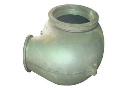
The hull of a cutter suction dredger plays a vital role in carrying most of the workpieces. It relies on the buoyancy of water to transport diesel, pumps, worktables, transmissions, hydraulic motors, and other components onto the water surface.
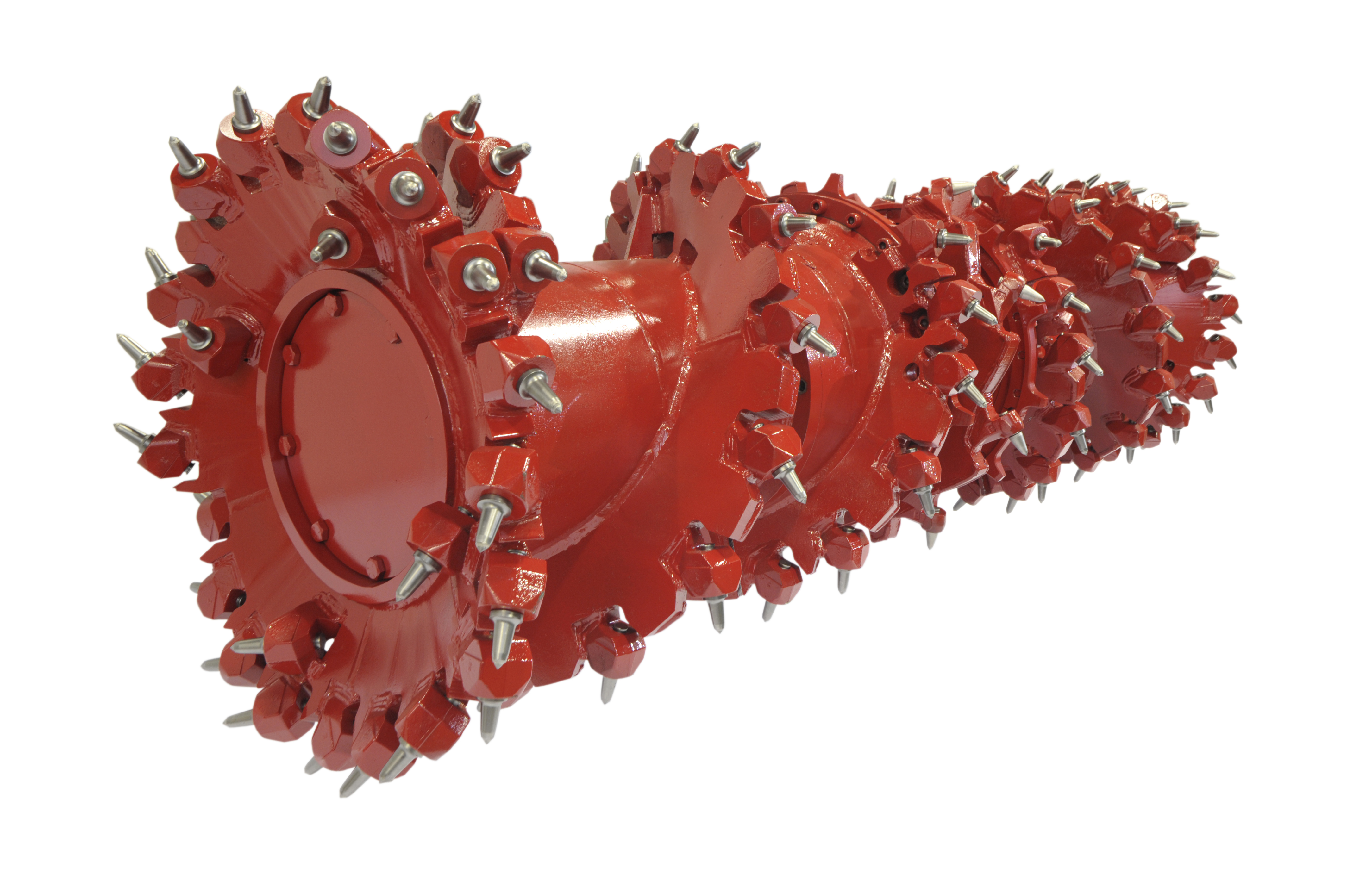
Cutter Suction Head: This component is primarily responsible for rotating the mud at the bottom of the pool into twisted leaves, causing it to boil. The sand pump then sucks the mud out through underwater suction pipes and transports it to a designated place on the coast through the discharge pipes. The suction head twists and sinks under the action of gravity, ensuring good contact with the pool bottom. Cutter Cage: Driven by a hydraulic motor, the cutter cage rotates. Due to the reaction force of the cutter blade, the entire hull rotates in the water with the position stake as the pivot point. Power Transmission: The working principle involves the diesel engine, transmission, gear pump, and cutter suction pipe. The high-speed centrifugal force generated by the operation of the mud pump, along with the diesel engine oil pump, hydraulic cylinder, and hydraulic motor, drives the cutter suction shaft to rotate.
The technical scheme adopted by the cutter mud sand dredger is designed to ensure efficient and reliable operations. The longitudinal hull of the sand pumping vessel is in an upward inclined shape with both ends. Two closed compartments are equipped at both ends of the hull, and one end of the compartment is fixed with a traction ring. The middle of the hull features a groove, where the diesel engine and sand extraction pump are sequentially installed from one end. The winch is installed on the bulkhead adjacent to the diesel engine, and the cooling nozzle of the diesel engine is connected to the water tank through a pipe.
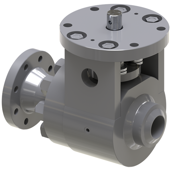
Sand Extraction Port: The side end of the sand pump is provided with a sand extraction port, which leads to the exterior of the ship through a partition board. A branch pipe with a valve is equipped on the pipe of the sand extraction port. Sand Discharge Pipes: The upper end of the sand pump has two sand discharge pipes, which are higher than the upper end of the hull. Guide Wheel and Bracket: A transverse connecting plate with a perforated base is fixed at the upper end of the sand extraction port. A guide wheel is fixed and installed in the middle of the two bases, with the base hole hinged to the bracket. A sliding guide roller is installed in the middle of the bracket, and connecting plates are installed at both ends of the bracket to connect the pillars. Marine Cable Supports and Battery Holder: Marine cable supports are installed at the four corners of the upper hull, and a battery holder is fixed at one end of the diesel engine. Connecting Frame and Winch: A connecting frame is provided between the two cabins at the upper end of the power shaft. A guide wheel is fixed in the middle of the connecting frame, and a winch is fixed at one end of the connecting frame. The pulley at the side of the winch is connected to the pulley on the diesel engine through a belt, and a steel wire rope is equipped on the winding shaft of the winch.
Bookmark
Daniel Féau processes personal data in order to optimise communication with our sales leads, our future clients and our established clients.


This site is protected by reCAPTCHA and the Google Privacy Policy and Terms of Service apply.