


EUR
en
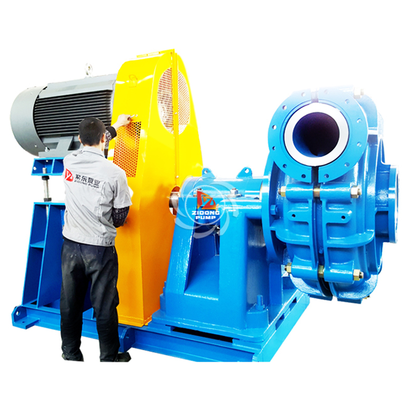
As a general rotating machinery product, the pump is mainly used for the transmission of liquid medium, and it is widely used in various industries such as petrochemical, water supply and drainage, agricultural irrigation and so on. Centrifugal pump refers to a pump that transports liquid by the centrifugal force generated by the rotation of the impeller. Centrifugal pumps can be widely used in electric power, metallurgy, coal, building materials and other industries to transport slurries containing solid particles. The R&D and production of centrifugal pumps are also developing rapidly. According to incomplete statistics, there are thousands of centrifugal pump factories in China. With the development of science and technology and the improvement of the automation degree of modern industrial instruments, the connection of each component of the instrument is getting closer and closer, and the pump products are developing in the direction of high speed, continuous and large scale. Centrifugal pump is one of the most important pump products, with a wide range of uses and advantages such as small size, light weight, high efficiency, stable performance and easy maintenance. People ignore the energy loss that may occur in actual production, which will not only cause damage to the centrifugal pump, but also cause a chain reaction to cause paralysis of the production system and serious economic impact. Therefore, it is very important to study the adjustment mode and energy consumption of the centrifugal pump, which is also a practical production problem that needs to be solved urgently.
Due to China’s strong support for new energy and the initiative of energy saving and emission reduction, important energy projects such as nuclear power plants and pumping hydropower stations are constantly developing, and centrifugal pumps are widely used in these important projects. The operating efficiency of the centrifugal pump is related to the high efficiency and energy saving of the pump and the system, and the adjustment method of the pump is related to the reliable operation of the pump and the system. The energy loss analysis based on the intelligent optimization algorithm and the selection of the adjustment mode of the centrifugal pump have become the important topics of the centrifugal pump research. This paper’s originality is the suggestion of the particle swarm algorithm prior to and following the improvement, which is based on the clever optimization technique. The algorithm’s global search capability enables it to swiftly identify the centrifugal pump’s proper adjustment mode and assess its energy usage. A comparative experiment is also conducted in the experimental phase to confirm the efficacy of the vulnerability algorithm suggested in this study.
The centrifugal pump is one of the most used pumps in the gas and oil industry, therefore this case study will describe the main component failure modes and maintenance tasks. The first step in FMEA is to define the equipment and the components list. The main component of a centrifugal pump can be described on the equipment hierarchy as shown in Fig.3.40.
The next step is to define the equipment and component function, which is described inn Table 3.18.
The next step is to define the component failure modes, cause, and consequences, which are defined in Tables 3.19–3.23.
There are different configurations of the risk matrix and such configurations must reflect the law and companies' risk policies. Fig.3.41 shows an example of a risk matrix with four severity categories and six frequency categories.
In addition, severity classification must describe all parties affected in case of an accident involving employees, the community, and the environment as well as company installation costs. Fig.3.42 shows an example of the severity category.
The pump is a widely used general purpose machine. Pumps work almost wherever liquids flow, and they are also used in various fields of industrial and agricultural production. Centrifugal pump is the most widely used pump at present, which has the characteristics of simple and reliable structure, small size, high efficiency, and convenient operation and maintenance. As the core equipment, centrifugal pumps play an important role in various fields such as hydraulic conveying, pumping irrigation, flood control and drainage engineering, and national economy(Wu et al., 2020). The centrifugal pump has a long history, its prototype was proposed as early as 1475, and the simple centrifugal pump appeared in 1680. The wide application of centrifugal pumps inevitably considers various energy consumption issues under various working conditions.
As shown in Fig.1: At present, the mathematical model of the centrifugal pump and its variation law are obtained by the method of fitting, which lays the foundation for the subsequent working point determination and flow adjustment(Nguyen et al., 2020). Momentum Theorem Dynamics is one of the universal theorems. It gives the relationship between the moment of momentum of the system of particles and the moment of impulse of the system of particles under mechanical action. Assuming an ideal situation where there are infinitely many and infinitely thin blades constituting the impeller, the basic Equation of the centrifugal pump is derived according to the theorem of moment of momentum and the triangle theorem of inlet and outlet velocity as Eq.(1):
H T is the theoretical head of the centrifugal pump, and the shape of the inlet of the centrifugal pump is generally designed to be conical, which is beneficial to increase the head and improve the hydraulic performance. Therefore, the direction of the absolute velocity of the liquid flow at the inlet of the impeller is perpendicular to the peripheral velocity, namely c 1 u=0, and its Equation can be simplified to Eq.(2):
It can be seen from the above Equation that the theoretical head H T of the centrifugal pump is related to the peripheral speed. The greater the liquid flow density, the greater the power consumption of the centrifugal pump. Considering that the centrifugal pump suffers from impact loss and friction loss during the actual operation, it is necessary to correct the obtained theoretical curve. A mathematical model that is closer to the actual working conditions is obtained(Aldosary et al., 2021; Liu et al., 2021).
Some scholars have carried out a variety of curve fitting analysis for centrifugal pump performance data, including exponential fitting and polynomial fitting. Analysis shows that the method using polynomial fitting meets the requirements in terms of accuracy and convenience(Sahu et al., 2021). Therefore, this paper also adopts this method to fit the flow and head characteristics of the centrifugal pump, such as Eq.(3):
In the Equation: a 1 is the quadratic term coefficient, a 2 is the primary term coefficient, a 3 is the constant term; Q is the flow rate of the centrifugal pump. The curve fitting analysis of centrifugal pump power is carried out by the same method, and the analysis shows that the accuracy of the polynomial fitting method meets the requirements. Therefore, this paper still uses this method to fit the power curve of the centrifugal pump(Xu and He, 2018). Curve fitting refers to selecting an appropriate curve type to fit the observed data, and using the fitted curve equation to analyze the relationship between two variables, such as Eq.(4):
In the Equation: b 1 is the quadratic term coefficient, b 2 is the primary term coefficient, b 3 is the constant term, and P j is the shaft power of the centrifugal pump.
The high-speed motor can drive the blades to generate a huge centrifugal force to compress working fluids, and the basic structure of the centrifugal pump is shown in Fig. 3 (d) [45]. Compared to positive displacement pumps such as claw and roots pumps, centrifugal pumps have the advantages of a high pressure ratio and compact design. The heart component of a centrifugal pump is the blade or impeller. Capurso et al. [60] proposed a new impeller structure by reducing the number of blades. The results showed that the optimal efficiency of the centrifugal pump could be improved by about 1%. Posa [61] found that changing the direction of diffuser blades was beneficial to the pump performance under off-design conditions. Derakhshan et al. [62] designed an impeller-optimized centrifugal pump with an efficiency improvement of 3.59%.
A centrifugal pump is a kinetic energy machine converting mechanical energy into hydraulic energy through centrifugal force. A detailed description of centrifugal pumps is discussed in _Volume 4_.
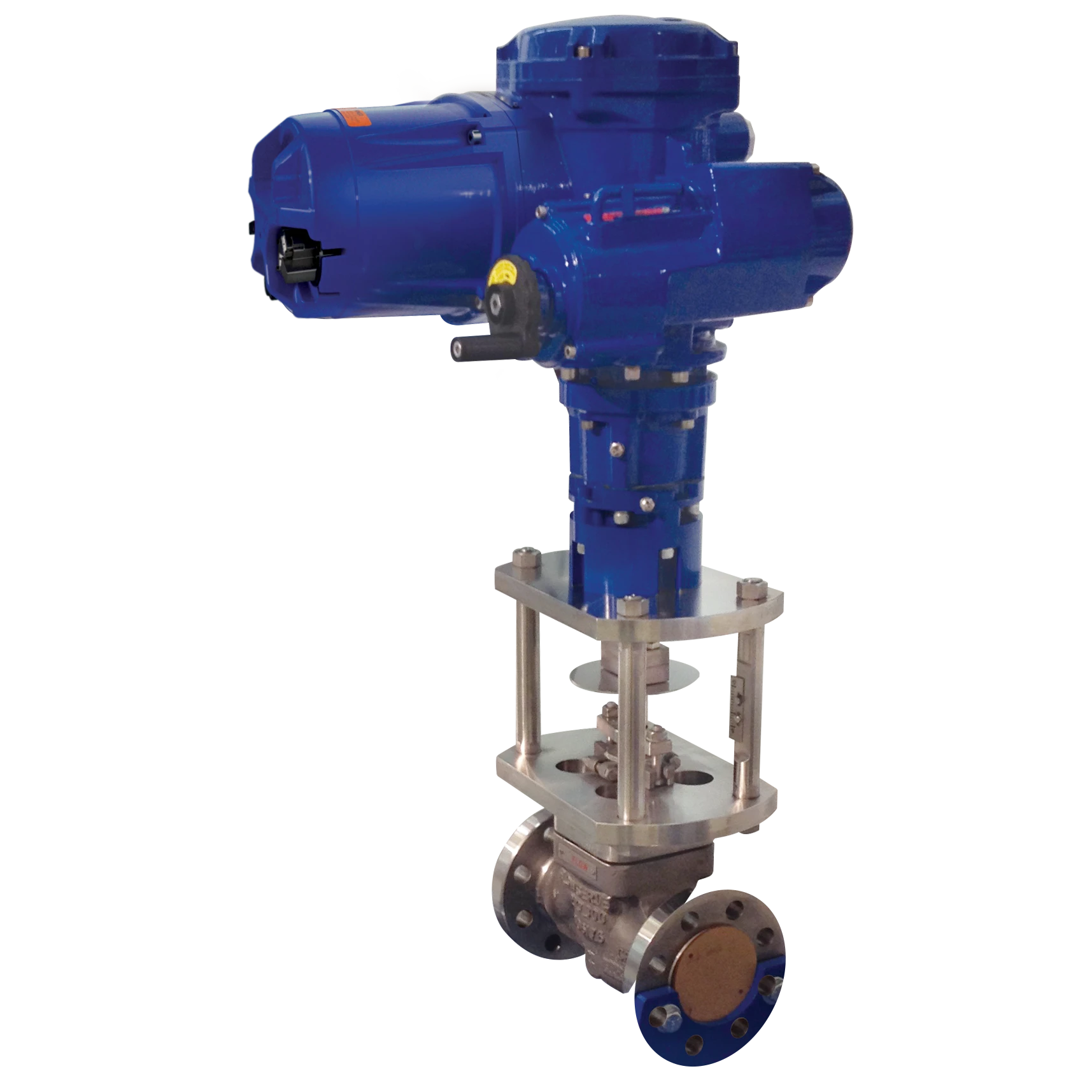
Over 80% of the pumps used in the oil and gas industries are of the centrifugal type. Figure 9.61 shows typical piping and fittings required at a centrifugal pump together with the valves necessary to isolate the pump from the system. The check valve is required to prevent possible flow reversal in the discharge line. A permanent in-line strainer is normally used for screwed suction piping and a temporary strainer for butt-welded/flanged piping. The temporary strainer is installed between flanges. A spool is usually required to facilitate removal.
Most pumps have end suction and top discharge. Limitations on space may require another configuration, such as top suction with top discharge and side suction with side discharge. The determination of nozzle orientation takes place when equipment layout and piping studies are made.
To avoid cavitation, the pump should be at the correct elevation, related to the level or head of the liquid being pumped. The suction line is a minimum of one pipe size larger than pump inlet. This minimizes the head losses. Suction lines should consider the following:
Route suction lines as directly as possible. This is done so as not to starve the pump and incur the risk of cavitation.
•If the pump draws liquid from a sump at a lower elevation, provide a combined foot valve and strainer. A centrifugal pump working in this situation requires priming initially. Thus, the designer should provide for this by a valve branch near the inlet port or by other means.
•Provide a strainer in the suction line. Do not place a temporary start-up screen immediately downstream of a valve as debris may back up and prevent the valve from being closed.
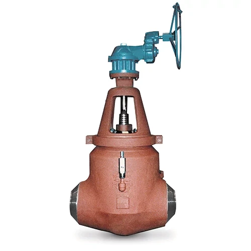
The suction valve should be a fully open gate valve.
The eccentric reducer should be installed with the straight side up. This avoids trapping noncondensing vapors and reduces the potential for cavitation.
The piping spool reduces turbulence before entering the pump junction. The removable spool piece should be provided in the piping for strainer removal.
The screen prevents solids from entering the pump. Temporary screens (strainers) should be fitted in all pump suction lines, downstream of the block valve, for start-up operation. Where permanent “Y”-type strainers are installed, one must check clearance for removal of the basket.
The outlet pipe for centrifugal and other non-positive-displacement pumps is in most cases chosen to be of larger bore than the discharge port, in order to reduce velocity and consequent pressure drop in the line. A concentric reducer or reducing elbow is used in the discharge line to increase the diameter. There is no restriction on the placement of elbows in discharge lines as there is in suction lines.
Unlike the suction line, there is no restriction on reducer type (i.e., concentric or eccentric is acceptable).
The check valve minimizes backflow, which can damage the pump.
The bypass to suction protects the pump from temperature buildup when the pumping rates are low. The line is designed to handle 20% of the pump's capacity at maximum discharge pressure with a line restrictor to adjust actual flow. For small pumps, the flow rate is usually controlled by an orifice or choke tube. For large pumps, a continuous bypass would consume excessive power; thus, a motor valve activated (opened) by low flow is used.
Centrifugal pumps have a wide range of application for transferring fluids in industrial operations. Centrifugal pumps are reliable and mechanically simple. Many chemical plants and refineries have hundreds of centrifugal pumps of various sizes conveying sundry liquids and slurries. These vital workhorses are used for water, flammable liquids, acids, caustics, and most other fluids.
Centrifugal pumps serve the industries well, but can be involved in accidents even if they are correctly sized and specified, made of the correct materials, and properly installed. Three pump incidents follow. This first case history involves an explosive incident that occurred during maintenance to remove a defective pump. Incidents two and three occurred during operations.
The centrifugal pump is the most important pump of the dynamic class of pumps for the oil and gas industry. Other pumps in this class are covered in other references [1, 4].
In its simplest form, a centrifugal pump consists of a rotating impeller (with radical vanes) rotating at a rather high speed. The rotating impeller is encased in a rigid housing that directs the liquid within the pump (see Figure 3.3.17) [1]. Liquid is supplied to the inlet that feeds the liquid to the center section of the rotating impeller. The rotational motion of the impeller forces the liquid, via the centrifugal forces, to move radically outward with the aid of the stationary diffuser. The rigid housing around the impeller guides the high-velocity fluid around the inside of the housing and out of the outlet of the pump.
The capacity of this type of pump depends on the pressure head against which the pump must act (see Figure 3.3.4).
When the liquid within the impeller is forced radially outward to the diffuser, a major portion of the velocity energy is converted into pressure energy by the stationary diffuser vanes (see Figure 3.3.17). This can also be accomplished by means of a volute, which is a part of the casing design (Figure 3.3.18) [1].
Centrifugal pumps with diffusion vanes are called _diffusion pumps_ or, more recently, _vertical turbine pumps_. Those pumps with volute casings are called _volute pumps_.
Centrifugal pumps can also be classified by the design of the impeller. Centrifugal pumps may have radial-flow impellers, axial-flow impellers, and mixed-flow impellers (both radial-flow and axial-flow).
Pump impellers are further classified as to the inlet flow arrangement such as single suction (which has a single inlet on one side) and double suction (which has a double inlet on each side of the impeller).
Impellers can be further classified with regard to their physical design: a closed impeller has shrouds or sidewalls enclosing the fluid flow, an open impeller has no shrouds or sidewalls, and a semiopen impeller is a mix of the closed and open design.
Another centrifugal pump classification is whether the pump is a single-stage pump (the pressure head is developed by a single impeller) or a multistage pump (the pressure head is developed by two or more impellers).
Centrifugal pumps can be further classified by physical design or axially split, radially split and whether the axis of rotation of the impeller(s) is vertical or horizontal. Horizontal pumps can be classified according as end suction, side suction, bottom suction, and top suction.
In applications, centrifugal pumps can be supplied with liquid via piping, or the pump may be submerged. Vertical pumps are called dry-pit or wet-pit types. The wet-pit pump (submerged) discharges up through a pipe system to some point above the pump.
There are important calculations that are needed to properly evaluate and select the appropriate centrifugal pump [6].
There are several similar relationships for centrifugal pumps that can be used if the effects of viscosity of the pumped fluid can be neglected. These relate the operating performance of any centrifugal pump for one set of operating conditions to the pump at another set of operating conditions, say conditions, and conditions 2.
The volumetric flow rate q (gpm) is related to rate q 2 (gpm) and the impeller speeds N 1 (rpm) and N 2 (rpm) by
The pressure head H 1 (ft) related to the head H 2 (ft) and impeller speeds N 1 and N 2 by
The pump input power P 1 (Lp) is related to the pump input power P 2 (hp) and impeller speed N 1 and N 2 by
For a constant impeller speed, the relationship between q 1, q 2, and impeller diameter D 1 (ft) and D 2 (ft) is
The heads are related by
and the power related by
The centrifugal pump specific speed N _ds_ (rpm) (or discharge specific speed) is
Pumps that operate by rotary action are called rotodynamic pumps and the centrifugal pump is the first type to be considered. Other types of pump still have their use, particularly for pumping chemicals, slurries and sludge, but the centrifugal pump is the most commonly used for pumping water because of the wide range of duties possible and the comparatively high efficiency and low cost. Centrifugal pumps are available in many different arrangements, as single or multistage units, and mounted vertically or horizontally to suit particular needs. The centrifugal pump comprises an impeller, which is rotated at high speed in a casing. All centrifugal pumps work on the principle set out above but their construction varies greatly according to the duty required. For example, multistage pumps, used to generate high heads, consist of several impellers and diffuser chambers arranged in series, the impellers being fixed to one shaft. The water from one diffuser chamber is led to the impeller of the next stage so that the pressure developed increases stage by stage.
Centrifugal pumps can be referred to as “dynamic” machines. They use centrifugal force for pumping liquids from one level of pressure to a higher level of pressure. Liquid enters the center of the rotating impeller, which imparts energy to the liquid. Centrifugal force then discharges the liquid through a volute as shown in Figure 4.3.1.
The centrifugal pump is one of the most widely used fluid handling devices in the refining and petrochemical industry. Every plant has a multitude of these types of pumps operating. A brief description of the various designs found in operating plants follows. Refer to Table 4.3.1 for the application limits of dynamic pumps.
The single stage overhung pump design shown in Figure 4.3.2 is probably the most widely used in the industry. Its construction incorporates an impeller affixed to a shaft which has its center of gravity located outside the bearing support system.
This type of pump is used in applications of low head, flow and horsepower. Refer to Figure 4.3.3.
The advantage of this pump design is that it can be mounted vertically (inline) between pipe flanges and does not require a baseplate. A concrete, grouted support plate, however, is strongly recommended. It should be noted that many inline designs do not incorporate bearings in the pump and rely on a rigid coupling to maintain pump and motor shaft alignment. Acceptable pump shaft assembled runout with these types of pumps should be limited to 0.001″.
This type of pump is used for low flow applications requiring high head. Refer to Figure 4.3.4. The pump case design is similar to the inline pump but incorporates pump bearings and an integral gear to increase impeller speeds from 3600 to over 30,000 RPM.
As the name implies, double suction impellers are mounted on between-bearing rotors as shown in Figure 4.3.5.
This pump design is commonly used when flow and head requirements make it necessary to produce low values of NPSH (Net Positive Suction Head required). When designing piping systems for this type of pump, care must be taken to assure equal flow distribution to each end of the impeller to prevent cavitation and vibration.
When the hydraulic limits of a single stage pump are exceeded, it is common practice to use a multistage pump shown in Figure 4.3.6.
This figure illustrates a horizontal split casing design which allows the rotor to be removed vertically after the top half casing is unbolted. This type of pump is normally limited to working pressure of approximately 2000 psi (136 bar), temperatures to 600°F (316°C), and S.G. of 0.7 or greater. Impeller configuration for this type of pump can be either “inline” or “opposed.” The “opposed” impeller arrangement has the advantage of not requiring a thrust balancing device which is required for the “inline” configuration.
The so-called barrel casing design is shown in Figure 4.3.7.
It is used for service conditions exceeding those normally considered acceptable for a horizontal split case design. A thrust balance device is required since the impeller configuration is almost always “inline.” The circular mounted end flange results in excellent repeatability for a tight joint as compared to a horizontal split case design. These pumps are used for charge pump, injection pump, and boiler feed pump applications.
There are a variety of vertical pump types and designs. Use of the vertical pump is usually dictated by low NPSH available. To provide adequate NPSH available characteristics, the first stage impeller and the entire pump is lowered in the ground. The can-type design shown in Figure 4.3.8 is one that is widely used in the petrochemical industry, particularly when pumping low specific gravity liquids from tank farm facilities. The multistage can pump is comprised of several bowl assemblies all contained within a can. This reduces the risk of hydrocarbon leakage to atmosphere. Lubrication to the sleeve bearings located throughout the length of the shaft is provided by the pumped liquid. Therefore bearing material vs product compatibility must always be considered. It is necessary, however, to prevent leakage where the shaft passes through the can to connect to the driver. Sealing is normally provided using a mechanical seal.
The sump pump illustrated in Figure 4.3.9 is a popular design for handling runoff streams of rainwater, noncorrosive or corrosive liquids. The setting depth limitation for this cantilever design is approximately 10 ft (3 m). This design incorporates an enclosed line shaft with external lubrication to the bottom bearing. The pump shaft and impeller are coupled to the driver which is supported by a motor support bracket bolted to a cover plate.
This type of pump consists of an electric motor driver coupled directly to the impeller/bowl assembly (see Figure 4.3.10).
All components are designed to be submerged in the pumped fluid. In the past, this type of pump did not find widespread use in the refining and petrochemical industry. However, with increasing environmental restrictions, this type of pump is being used more frequently in the refining and petrochemical industry.
As a result of more stringent environmental constraints and regulations, sealless pump technology has gained prominence. One such design is the magnetic drive pump (MDP) shown in Figure 4.3.11. This is a design such that the motor shaft is attached to the power frame of the magnetic drive pump by means of a flexible or rigid coupling. The outer magnet and shaft assembly is supported by its own bearings. Alignment requirements for this type of pump are similar to that for horizontal mounted centrifugal pumps fitted with mechanical seals or packing. The sealless pump is generally applied when there is a need to contain toxic or hazardous fluids.
Centrifugal pumps often operate at high or very high rotational speeds. This means that they are less suitable for pumping of protein solutions. In biotech applications, they may be used for handling WFI and various buffer solutions. Centrifugal pumps have a rotating impeller that is driven by an electrical motor.
Bookmark
Daniel Féau processes personal data in order to optimise communication with our sales leads, our future clients and our established clients.


This site is protected by reCAPTCHA and the Google Privacy Policy and Terms of Service apply.