


EUR
en
Engineering data 01 SVA Cool. F.W. & S.W. Pumps 03 SVB Fire & G.S. Pumps 09 RVP Fire & G.S. Pumps 13 RVX Fire & G.S. Pumps 17 SA Lubricating Oil Pumps 19 HJ F.W. & Sanitary Pumps 21 GJ Miscellaneous Cool. W. Pumps 23 AHJ F.W. & Sanitary Pumps 25 SVQ Boiler Feed Pumps 27 SHQ Boiler Feed Pumps 29 SK Boiler Feed Pumps 31 GHQ Boiler Feed Pumps 33 DK Boiler Feed Pumps 35 DK80-10M Boiler Feed Pumps 37 DK100-8M Boiler Feed Pumps 39 BT-4 Boiler W. Circulating Pumps 41 UH Hydrophore Units 43 UH153L Hydrophore Units 47 CVF.CVN Condenser Circulating Pumps 49 EVZ Condensate Pumps 53 RVZ Condensate Pumps 55 RVE Condensate Pumps 57 UC Cascade Tank Units 59
SHINKO marine centrifugal pumps have been designed and manufactured in accordance with the Japan Ship Machinery and Equipment Association’s standards for high performance under the following operating conditions: Temperature : Maximum ambient temperature : 50 ℃ : Maximum cooling sea water temperature : 32 ℃ List and rolling of the ship : 15 degrees horizontally, 10 degrees longitudinally, and 22.5 degrees for one side rolling. Installation direction : The shafts for the horizontal pumps are to be installed parallel to the keel. The shafts for the vertical pumps are to be installed vertically to the keel.
○H-Q CURVE All pumps are designed in such a way that the H-Q curve descends to the right in a continuous line as shown in the figure on the right. At any of the points on the H-Q curve, shaft horsepower does not exceed motor output. However, some specific pumps such as boiler feed pumps, condensate pumps, and drinking water pumps or sanitary pumps for hydrophore units, are operated within a specific range upon which the motor output is selected. Hence, shaft horsepower beyond this specific range may exceed the motor output. ○BALL BEARINGS & LUBRICATION The vertical models SA, SB, CVF, EVZ, and all horizontal pumps except the model HJ are equipped with heavy duty deep groove ball bearings or angular contact ball bearings. Sealed ball bearings are applied to small pumps. Whereas, all other pumps use grease lubrication or oil lubrication. For oil lubrication, either an oil bath or an oil ring is employed to lubricate. And, an oil level gauge is located on the bearing housing. During the shop test, attention has been paid to the bearing temperature of electric-motor-driven pumps to ensure that they do not exceed the ambient temperature by 40 ℃ or liquid temperature by 20 ℃ whichever is higher, and do not exceed 75 ℃ in summer. ○LINE BEARING & LIQUID LUBRICATION We have experienced many troubles to do with the lower side bearings such as water leakage from the stuffing box causing the ball bearings to get rusty in the vertical pumps. And, with our standard pumps, the lower bearings are equipped with a line bearing where water lubrication is applied utilizing a pump discharge liquid. The line bearing is also applied to the casing and intermediate shaft bearings of the tank mounting pumps (the models SA and SB). ○VIBRATION Consideration has been given to the design of the pump construction and the impellers to reduce vibration as much as possible. The maximum tolerance for pump vibration during shop test is shown on the table on the right. ○NOISE Consideration has been given to the design of the pump casings and the impellers to reduce as much noise as possible as with vibration. The permissible value of the noise in the shop to be less than 100 dB (A), when measuring at 1 m distance from the pump operated at rated condition. ○PRESSURE GAUGE & ROOT VALVE To indicate pump suction pressure and discharge pressure, 75 mm diameter gauges are fitted onto a gauge stand for horizontal pumps or onto a gauge board for vertical pumps. Connection to the gauges is made via 6mm outer diameter copper pipes with root gauge valves on the pump side, and gauge joints on the gauge side. ○COUPLING COVER A coupling cover is provided for the pumps for safety. ○AIR VENT VALVE At the highest point of the pump casing, a hole is provided to allow the air to vent, and an air vent valve is installed.
APPLICATIONS Jacket cooling fresh water pumps Sea water service pumps Other use GENERAL CHARACTERISTICS (SINGLE SUCTION) Model Item SVA 100 SVA 125 SVA 125-2 SVA 150 SVA 150-2 SVA 200B Rotation Clockwise when viewed from the driver Suction bore (mm) 100 125 125 150 150 200 Discharge bore (mm) 100 125 125 150 150 200 Stuffing box seal Gland packing or Mechanical seal Max.output (kW) 15 22 37 30 45 30 weight:CAC (kg) 175 195 270 230 280 235 weight:FC (kg) 165 175 250 210 260 215 Water filled in casing (kg) 6 18 26 25 33 37 PERFORMANCE CHARTS Dimensions:mm
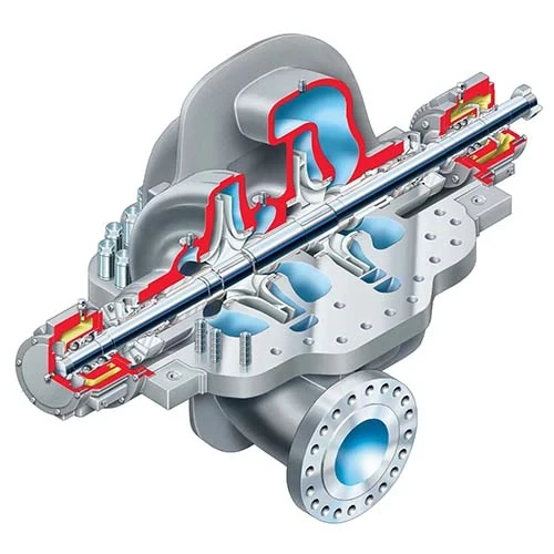
APPLICATIONS Cooling sea water pumps Cooling fresh water pumps Turbo generator condenser C.S.W. pumps Vaccum condenser C.S.W. pumps Inert gas scrubber C.S.W. pumps Reliquefaction C.F.W. pumps Central cooling sea water pumps Central cooling fresh water pumps Ballast pumps Others GENERAL CHARACTERISTICS (DOUBLE SUCTION) Model Item SVA 200 SVA 250B SVA 250(A) SVA 300B SVA 300(A) Rotation Clockwise when viewed from the driver Suction bore (mm) 200 250 250 300 300 Discharge bore (mm) 200 250 250 300 300 Stuffing box seal Gland packing or Mechanical seal Max.output (kW) 45 55 90 75 132 weight:CAC (kg) 360 300 460 350 570 weight:FC (kg) 310 260 400 315 510 Water filled in casing (kg) 51 76 90 101 125 Model Item SVA 350B SVA 350(A) SVA 400(A) SVA 450 SVA 500X SVA 600X Rotation Clockwise when viewed from the driver Suction bore (mm) 350 350 400 450 500 600 Discharge bore (mm) 350 350 400 450 500 600 Stuffing box seal Gland packing or Mechanical seal Max.output (kW) 110 150 280 315 460 600 weight:CAC (kg) 420 730 1160 1600 1800 2370 weight:FC (kg) 380 675 1050 1450 1640 2160 Water filled in casing (kg) 126 195 315 438 668 850 Dimensions:mm
For Cooling Sea Water Pumps and Cooling Fresh Water Pumps (SVA) For Turbo Generator Condenser Cooling Pumps (SVA) Pumps should be used intermittently when they are run in the gray-colored zones on the charts below.
APPLICATIONS Fire and general service pumps Bilge and ballast pumps Emergency fire pumps Other use GENERAL CHARACTERISTICS (SINGLE SUCTION) Model Item SVB 65 SVB 100 SVB 125 Rotation Clockwise when viewed from the driver Suction bore (mm) 65 100 125 Discharge bore (mm) 65 100 125 Stuffing box seal Gland packing or Mechanical seal Max.output (kW) 15 30 75 weight:CAC (kg) 165 185 255 weight:FC (kg) 150 165 230 Water filled in casing (kg) 4 6 18 APPLICATIONS Fire and general service pumps Bilge and ballast pumps Emergency fire pumps Other use GENERAL CHARACTERISTICS (DOUBLE SUCTION) Model Item SVB 150 SVB 200 Rotation Clockwise when viewed from the driver Suction bore (mm) 150 200 Discharge bore (mm) 150 200 Stuffing box seal Gland packing or Mechanical seal Max.output (kW) 110 150 weight:CAC (kg) 320 410 weight:FC (kg) 280 360 Water filled in casing (kg) 42 62 Dimensions:mm
APPLICATIONS Fire and general service pumps Bilge and ballast pumps Emergency fire pumps Other use GENERAL CHARACTERISTICS Model Item RVP 100 RVP 130 RVP 160 RVP 160-2 RVP 200 RVP 200-2 RVP 250-1 RVP 250 Rotation Clockwise when viewed from the driver Suction bore (mm) 100 125 150 150 200 200 250 250 Discharge bore (mm) 100 125 150 150 200 200 250 250 Stuffing box seal Gland packing or Mechanical seal Max.output (kW) 18.5 45 55 110 110 150 200 450 weight:CAC (kg) 265 412 560 590 670 685 755 800 weight:FC (kg) 240 370 510 535 605 630 675 715 Water filled in casing (kg) 10 21 41 51 70 80 105 110 Dimensions:mm
For fire and general service pumps, a double specification is required. And, for emergency fire pumps, a single specification is required. The dashed double-dotted lines are used when a pump has a double specification. ※ Please contact us if you have double or more specifications.
APPLICATIONS Fire and general service pumps Bilge and ballast pumps Other use GENERAL CHARACTERISTICS Model Item RVX 160S RVX 200S RVX 260S Rotation Clockwise when viewed from the driver Suction bore (mm) 150 200 250 Discharge bore (mm) 150 200 250 Stuffing box seal Gland packing or Mechanical seal Max.output (kW) 55 55 132 weight:CAC (kg) 700 730 885 Water filled in casing (kg) 45 66 105 PERFORMANCE CHARTS Dimensions:mm
Vertical single-suction axial-fl ow tank-mounting In order to standardize the length (L), the dimension (S) is adjusted to the range shown in the table below depending on the tank height (H). Model H(reference) S L(reference) P M(S + P) SA 150 (-2) 2080~2180 80~180 2000 250 330~430 SA 200 (-2) 2100~2200 100~200 250 350~450 SA 250 (-2) 2120~2220 120~220 310 430~530 SA 300 (-2) 2140~2240 140~240 360 500~600 SA 300H 2140~2240 140~240 360 500~600 SA 350 (-2) 2170~2270 170~270 400 570~670 SA 350H 2120~2270 170~270 400 570~670 SA 400 (-2) 2220~2320 220~320 480 700~800 APPLICATIONS Lubricating oil pumps GENERAL CHARACTERISTICS Model Item SA 150 SA 150-2 SA 200 SA 200-2 SA 250 SA 250-2 SA 300 SA 300H SA 300-2 SA 350 SA 350H SA 350-2 SA 400 SA 400-2 Rotation Clockwise when viewed from the driver Number of stages 1 2 1 2 1 2 1 1 2 1 1 2 1 2 Discharge bore (mm) 150 200 250 300 350 400 Max.output (kW) 37 75 75 90 110 150 150 200 315 250 280 400 450 450 Lubrication Self-Iubrication by handling oil Reqired min. LO leve (mm) 330 350 430 500 570 700 Stuffing box seal Oil seal weight:FC (kg) 510 (40) 580 (40) 770 (50) 900 (50) 1070 (63) 1230 (63) 1170 (80) 1220 (80) 1350 (80) 1530 (108) 1590 (108) 1730 (108) 1650 (120) 2100 (120) Weight refers to L=2m, and increases as shown in bracket with 1m increases in L SAD : A single shaft without an intermediate bearing SAE : Two shafts with sleeve couplings SAF : A single shaft with an intermediate bearing SAG : Two shafts with sleeve couplings and an intermediate bearing PERFORMANCE CHART Handling lube oil with a viscosity of 100 cSt and a specific gravity of 0.9 at 40 ℃ Capacity guarantee : 25.8 cSt Power guarantee : 260 cSt Dimensions:mm
APPLICATIONS Fresh water pumps Sanitary pumps Refrigerator cooling water pumps Other use GENERAL CHARACTERISTICS Model Item HJ 40-2 Rotation Clockwise when viewed from the driver Suction bore (mm) 40 Discharge bore (mm) 40 Stuffing box seal Gland packing or Mechanical seal Max.output (kW) 7.5 weight:CAC (kg) 41 weight:FC (kg) 38 Water filled in casing (kg) 0.8 PERFORMANCE CHART Dimensions:mm
APPLICATIONS Air conditioning ref. cooling water pumps Refrigerator cooling water pumps Miscellaneous cooling water pumps Fresh water generator ejector pumps Other use GENERAL CHARACTERISTICS Model Item GJ 40-20 GJ 40-25 GJ 50-20 GJ 50-25 GJ 80-20 GJ 80-25 Rotation Clockwise when viewed from the driver Suction bore (mm) 50 50 80 80 100 100 Discharge bore (mm) 40 40 50 50 80 80 Stuffing box seal Gland packing or Mechanical seal Max.output (kW) 11 18.5 18.5 30 7.5 15 weight:CAC (kg) 140 151 145 161 186 232 weight:FC (kg) 132 141 136 150 174 219 Water filled in casing (kg) 1.6 2.1 2.8 3.4 4.8 5.8 PERFORMANCE CHARTS When this model is used for pumps with a total head below 30m, such as air conditioning refrigerator cooling pumps, the revolution of the electric motor is 1800m -1 and the upper chart should be referred to. On the other hand, when this model is used for pumps with a total head over 30m, such as fresh water generator ejector pumps, the speed of the electric motor is 3600m -1 and lower chart should be referred to. If the rated point is within the performance chart, even when the total head is between 20~30m, the lower chart for 3600min -1 can also be used. Dimensions:mm
APPLICATIONS Fresh water pumps Sanitary pumps Other use GENERAL CHARACTERISTICS Model Item AHJ 50-2 AHJ 70-2 Rotation Clockwise when viewed from the driver Suction bore (mm) 50 65 Discharge bore (mm) 50 65 Stuffing box seal Gland packing or Mechanical seal Max.output (kW) 5.5 7.5 weight:CAC (kg) 130 210 weight:FC (kg) 115 180 Water filled in casing (kg) 7 12 PERFORMANCE CHART Dimensions:mm
APPLICATIONS Feed pumps for exhaust gas boilers on diesel ships GENERAL CHARACTERISTICS Model Item SVQ50(L) SVQ50A Type Vertical Horizontal Rotation CW(CCW) when viewed from the driver Suction bore (mm) 50 Discharge bore (mm) 50 Stuffing box seal Gland packing or Mechanical seal MAX.output (kW) 18.5 weight:FC(FCD) (kg) 110 Water filled in casing (kg) 6 PERFORMANCE CHART Note : When attaching two pumps to the cascade tank wall, symmetrical pumps can be used.
APPLICATIONS Feed pumps for exhaust gas boilers on diesel ships GENERAL CHARACTERISTICS Model Item SHQ 65 Rotation Clockwise when viewed from the driver Suction bore (mm) 65 Discharge bore (mm) 65 Stuffing box seal Gland packing or Mechanical seal Max.output (kW) 30 weight:FC(FCD) (kg) 180 Water filled in casing (kg) 7 PERFORMANCE CHART Dimensions:mm
APPLICATIONS Feed pumps for exhaust gas boilers on diesel ships Cold start feed pumps for LNG carriers GENERAL CHARACTERISTICS Model Item SK 40 Rotation Clockwise when viewed from the driver Suction bore (mm) 40 Discharge bore (mm) 40 Stuffing box seal Gland packing or Mechanical seal Max.output (kW) 30 weight:FC(FCD) (kg) 240 Water filled in casing (kg) 9 PERFORMANCE CHART Dimensions:mm
APPLICATIONS Feed pumps for cargo boilers on diesel ships GENERAL CHARACTERISTICS Model Item GHQ 100-2 Rotation Clockwise when viewed from the driver Suction bore (mm) 100 Discharge bore (mm) 100 Stuffing box seal Gland packing or Mechanical seal Max.output (kW) 110 weight:FCD (kg) 300 Water filled in casing (kg) 10 PERFORMANCE CHART Dimensions:mm
APPLICATIONS Feed pumps for cargo boilers on diesel ships GENERAL CHARACTERISTICS Model Item DK 80-4 DK 100-4 Rotation Clockwise when viewed from the driver Suction bore (mm) 100 125 Discharge bore (mm) 80 100 Lubrication system Oil ring LO required (ℓ) 0.7 Stuffing box seal Gland packing or Mechanical seal Max.output (kW) 110 185 weight:FCD (kg) 910 1100 Water filled in casing (kg) 38 48 PERFORMANCE CHART Dimensions:mm
APPLICATIONS Feed pumps for main or auxiliary boilers GENERAL CHARACTERISTICS Model Item DK 80-10M Rotation Clockwise when viewed from the driver Suction bore (mm) 100 Discharge bore (mm) 80 Lubrication system Oil ring LO required (ℓ) 1.3 Cooling F.W.required (m 3/h) 4 (Below 36 ℃) Stuffing box seal Mechanical seal Max.output (kW) 355 weight (kg) 2350 Water filled in casing (kg) 68 PERFORMANCE CHART
APPLICATIONS Feed pumps for main or auxiliary boilers GENERAL CHARACTERISTICS Model Item DK 100-8M Rotation Clockwise when viewed from the driver Suction bore (mm) 125 Discharge bore (mm) 100 Lubrication system Oil ring LO required (ℓ) 1.3 Cooling F.W.required (m 3/h) 4 (Below 36 ℃) Stuffing box seal Mechanical seal Max.output (kW) 520 weight (kg) 2400 Water filled in casing (kg) 70 PERFORMANCE CHART
APPLICATIONS Boiler water circulating pumps GENERAL CHARACTERISTICS Model Item BT 50-4 BT 70-4 BT 100-4 BT 100-4A BT 125-4 Rotation Clockwise when viewed from the driver Suction bore (mm) 50 65 100 125 150 Discharge bore (mm) 50 65 100 100 125 Amount of LO filled (ℓ) 0.67 (turbine OIL ISO VG-68) Stuffing box seal Mechanical seal Max.output (kW) 5.5 15 18.5 30 75 weight:FCD (kg) 155 192 245 255 550 Water filled in casing (kg) 2 3 3 4.5 20 Dimensions:mm NOTE : Cooling fresh water for mechanical seal Figures in parentheses show dimensions for BT125-4 Quantity 1.2m 3 /h Pressure 0.1MPaG Inlet water temp. below 60 ℃ PERFORMANCE CHART
APPLICATIONS Hydrophore units for drinking water Hydrophore units for fresh water Hydrophore units for sanitary water GENERAL CHARACTERISTICS FOR A SINGLE-TANK UNIT Model Item UH 051 UH 101 UH 102 UH 152 UH 202 Tank volume (m 3) 0.5 1.0 1.0 1.5 2.0 Number of pumps supplied 1 1 2 2 2 Pump type Vertical single stage centrifugal Capacity × head 5~15m 3/h × 40~60m Pump suction bore (mm) 40 Tank outlet bore (mm) 50 Max.output (kW) 7.5 Weight (kg) 400 490 560 630 700 weight at service condition 0.5MPaG (kg) 750 1190 1260 1680 2100 Dimensions:mm
The inside of the tank is coated with pure epoxy after being thoroughly cleaned with a sandblasting process.
APPLICATIONS Hydrophore units for drinking water and fresh water GENERAL CHARACTERISTICS FOR A CONBINED-TANK UNIT Model Item UH 153L Kind of liquid Fresh water Drinking water Tank volume (m 3) 1.0 0.5 Number of pumps supplied 2 1 Pump type Vertical single stage centrifugal Capacity × head 5~15m 3 /h × 40~60m Pump suction bore (mm) 40 Tank outlet bore (mm) 50 Max.output (kW) 7.5 Weight (kg) 1000 weight at service condition 0.5MPaG (kg) 2050 In order to conserve space in the engine room, this combined hydrophore tank is designed to integrate two tanks into one. The tank is separated horizontally by a dished-end plate. The lower side can hold 1m 3 of fresh water and the upper can hold 0.5m 3 of drinking water. One fresh water pump and one drinking water pump have been simply installed on the combined tank. They are connected with the tank via a screw-down-check valve to supply the water. Additionally, one spare pump with an electric motor has been installed on the tank simply. If either of the pumps malfunction, they can be replaced with this pump. PERFORMANCE CHART PAINTING The inside of the tank is coated with pure epoxy after being thoroughly cleaned with a sandblasting process.
APPLICATIONS Main condenser circulating pumps T/G condenser circulating pumps GENERAL CHARACTERISTICS Model Item CVF 600 CVN 600 CVF 700 CVN 700 CVF 850 CVN 850 CVF 1000 CVN 1000 Rotation Clockwise when viewed from the driver Suction bore (mm) 600 700 850 1000 Discharge bore (mm) 600 700 850 1000 Flow direction 90° 180° 90° 180° 90° 180° 90° 180° Stuffing box seal Gland packing or Mechanical seal Max.output (kW) 110 150 250 355 weight:CAC (kg) 2930 2830 3830 3730 5200 5150 8500 8500 Water filled in casing (kg) 920 870 1210 1165 1695 1620 3300 3300 Dimensions:mm
APPLICATIONS Main condensate pumps Drain transfer pumps Other use GENERAL CHARACTERISTICS Model Item EVZ 50 EVZ 70 EVZ 100 EVZ 130 EVZ 130-2 EVZ 150 Rotation Clockwise when viewed from the driver Suction bore (mm) 100 125 200 250 250 300 Discharge bore (mm) 50 65 100 125 125 150 Stuffing box seal Gland packing or Mechanical seal Max.output (kW) 22 22 45 55 90 150 weight:FC (FCD) (kg) 200 470 530 590 640 760 Water filled in casing (kg) 7 24 27 48 58 68 1st stage impeller : Single suction for EVZ 50, 70, and 100 Double suction for EVZ 130, 130-2, and 150 PERFORMANCE CHART Dimensions:mm
APPLICATIONS Condensate pumps for turbo generators GENERAL CHARACTERISTICS Model Item RVZ 50 Rotation Clockwise when viewed from the driver Suction bore (mm) 100 Discharge bore (mm) 50 Stuffing box seal Gland packing or Mechanical seal Max.output (kW) 3.7 weight:FC (kg) 175 Water filled in casing (kg) 7 PERFORMANCE CHART
APPLICATIONS Condensate pumps Drain transfer pumps Other use GENERAL CHARACTERISTICS Model Item RVE 70 RVE 100 RVE 130 Rotation Clockwise when viewed from the driver Suction bore (mm) 125 200 250 Discharge bore (mm) 65 100 125 Balance pipe (mm) 25 Stuffing box seal Gland packing or Mechanical seal Max.output (kW) 7.5 18.5 22 weight:FC (kg) 175 288 358 Water filled in casing (kg) 10 28 29 PERFORMANCE CHART Dimensions:mm
APPLICATIONS An atmospheric condenser and feed pumps are combined with the cascade tank as a single unit, which helps to minimize the installation space required. Wasted condensation water, which has heated up fuel oil for the main engine or other components, is led to the atmospheric condenser to be cooled. Then, the oil mixed in with the condensation water is removed with sponges in the buckets installed in the cascade tank. The clean water is fed to the auxiliary boiler via the feed pump. GENERAL CHARACTERISTICS Model Item UC 102 UC 152 UC 202 Cascade tank Overflow capacity (m 3) 2.0 2.6 2.9 Effective water quantity (m 3) 1.0 1.5 2.0 Feed pump Number of pumps supplied CW:1, CCW:1 Pump type Centrifugal Capacity (m 3/h) 2.5 2~6 2~10 Total head (m) 110 100~140 100~140 Max.output (kW) 18.5 Atmos. Condenser Type of condenser Shell & tube Cooling surface (m 2) 8~10 8~10 8~14 Steam drain quantity (kg/h) 1000 1200~1800 1200~2500 Cooling S.W.required (m 3/h) 25 35~55 45~70 Weight Dry (kg) 2000 2550 3300 Operating (kg) 3850 4850 6550
PERFORMANCE CHART SYSTEM DESIGN (in the case of UC 152)
Bookmark
Daniel Féau processes personal data in order to optimise communication with our sales leads, our future clients and our established clients.


This site is protected by reCAPTCHA and the Google Privacy Policy and Terms of Service apply.