


EUR
en
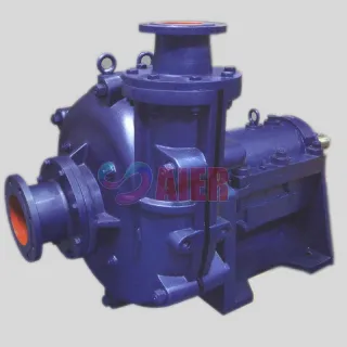
Our last discussion centered around the definition of a cantilever pump and how shaft deflection issues can determine maximum setting length. Today, I would like to focus on agitator pumps and leave non-agitator pumps for another day. For those readers who are unfamiliar with the term “agitator pump”, it is simply a pump design where the main pump shaft extends past the impeller hub so an agitator can be mounted just in front of the suction inlet. The agitators is there to resuspend solids so they can be pumped along with the surrounding liquid. Agitator pumps are generally associated with solids suspension and pumping slurry. Within that definition, cantilever agitator pumps are used anywhere a vertical pump, with a setting length of approximately. 7 ft or shorter is required. This covers a wide range of applications,but by far and away the most numerous is a collection sump. Prior to the advent of cantilever pumps, vertical column pumps or submersible pumps were the only choice for sumps.
Conventional grease or oil-lubricated bearings must be isolated from water and solid contamination. This means that the bearings used to support the rotating elements in conventional vertical or submersible pumps must have seals to protect them from contamination. Submerged seals have a finite operating life, especially in slurry applications. When seals fail users are subject to downtime and expensive repairs. Cantilever pumps require no submerged bearings and therefore require no submerged seals. This is a key feature of cantilever pumps!!!
With cantilever agitator pumps being limited to settings in the area or 7 ft, it is only reasonable to compare them with vertical column pumps of similar setting length. The much smaller shafts and support structures of the column pump make them lighter. The cost savings in steel are somewhat offset by the extra cost of the seals in their wet end.However, any slight advantage either pump may have in capital cost is a non-issue,as capital cost is greatly overshadowed by the reliability and associated cost saving of the cantilever design. This, of course, stems from the cantilever design eliminating all submerged seals or bearings. As suc,h I will, for the balance of today, drop the vertical column pump as an alternative to a cantilever pump.
Cantilever pumps have separate detachable motors. Generally speaking, the motor is an off-the-shelf standard “T” or “TC” frame. This allows for quick and easy re and re of the motor. It also may allow the user to increase the motor size if operating conditions call for more power. Any increase in motor size would, of course,have to be done within the original design restraints of the pump assembly. Submersibles have no such ability.
Both submersible and direct drive cantilever pumps require a variable frequency drive to modify pump speed to adjust for any change in operating conditions. Cantilever pumps are often purposely built as a V-belt driven pump, knowing that speeds may easily be altered with a quick and inexpensive change of sheaves and belt. Advantage cantilever!
As soon as the motor is separated from a cantilever, it becomes a purely mechanical device. As such, a standard maintenance department has no issues accepting it for repair. Submersibles, on the other hand, are often thought of as an electric motor and sent to the electric shop. The electric shop, however, sees it as a pump and refuses to work on it. This problem is generally resolved by sending the submersible off-site for repairs, both costly and consuming. Another point for cantilevers!
Assuming the windings on a submersible are okay, it is possible for any maintenance shop to facilitate a repair. The personnel working on the pump, however, need to be the type of individual who takes pride and care with the repair. Mistakes as simple as a pinched o-ring will result in a complete failure when the pump is reinstalled. A cantilever pump, on the other hand, is a simple, robust piece of equipment that anyone can repair should the need arise.
Submersible pumps all have submerged seals, and often the first sign of seal failure in a submersible is the pump’s electrics tripping out as water reaches the motor windings. This failure, happening with no warning, can lead to a facility scrambling to counter rising water levels. Conversely, most cantilever failures/problems occur over time and, as such, can be scheduled for maintenance as time allows
Submersible pumps are clearly an alternative to cantilever pumps, and in small horsepower applications, the low initial cost can make them quite attractive. This advantage, however disappears as the size of the unit increases. Somewhere around 10 hp, a crossover happens and a cantilever unit requires less initial investment than an equivalent submersible agitator slurry pump.
The ease with which cantilever pumps can be adapted to meet different conditions (with belt drives) allows one pump size to be used in different applications requiring different flows and heads. This standardization minimizes spare pumps and or parts inventory, and allows the pump manufacturer to batch manufacture and pass on the savings in the form of lower pump prices.
Today I think we have shown a pretty strong case for opting to a vertical cantilever pump over a submersible. That is not to say that all short setting sump applications must be cantilevers, but it is probably fair to say that cantilevers would be a good choice in many cases. Before leaving today… I am sure someone will ask, “Well what about deep sumps??” Stay tuned, next time we will answer that question.
“Vertical cantilever pumps”, as the name implies, are pumps designed to operate with the shaft running in a vertical plane with some sort of cantilever component in their design. The shaft running in a vertical plane is self-explanatory,but the term “cantilever component” may require a quick explanation. Rotating shafts/assemblies are normally supported by two bearing points. Some pumps have an impeller mounted between the bearing points, while some impellers are mounted outboard of the bearing points. When the impeller is mounted outboard of the bearings but in close proximity to them,the design is referred to as an“overhung” design. If the impeller is purposely mounted with a significant overhung length (distance away from the bearing points), it is still an overhung design but is generally referred to as a cantilever design. So why build a vertical pump with the impeller mounted so far from the support points? Surely it increases all the loads within the pump. Well, it does, but it also distances the bearings from the pumpage and therefore allows the elimination of the seals in the wet end, which is a significant source of failure for standard overhung pumps. This is particularly true with slurry pump,s where the abrasive nature of some slurries can lead to extremely short seal life.
In the previous paragraph, I mentioned increased loads. Well, yes, the further a force is from the support the greater the mechanical advantage, and therefore the greater the forces on the entire structure. In a rotating assembly, vibration is a killer and often a result of shaft deflection, causing an imbalance or just plain balance issues. The long overhang associated with vertical cantilever pumps makes this design of pump very susceptible to shaft deflection issues, and engineers pay particular attention to this aspect of design. To quantify this, the load increases to the fourth power as the overhang increases. That means if you double the overhung distance,you increase the deflection by a factor of 16 and very quickly create a destructive imbalance.
Engineers control the deflection and vibration in a cantilever shaft by adjusting the distance between the bearing points, increasing the diameter of the shaft, altering the material the shaft is made of, and, of course,specifying operational parameters. The selection of material is pretty easy. You generally avoid materials that stress relieve over time or have a low modulus of elasticity (bend easily). This means opting for materials like 4140 for general applications or 174ph for some more corrosive applications is usually a good choice. Increasing the diameter of a shaft to control defection is the simplest solution, but you can only go so far before problems arise. With deflection increasing by the fourth power, you quickly require a very thick and heavy shaft. As the diameter increases, it becomes impossible to find bearings that can support a very large shaft and sustain any decent operating RPM. In short,the peripheral speed of the bearings becomes too fast for the rating of any bearing strong enough to handle the load. Shortening the distance between the bearings can minimize deflection between the bearings and therefore greatly alter the deflection at the impeller. However, as the simplified load sketch below illustrates, halving the distance between the bearings increases the radial load on both bearings. These same bearings may also be under duress from the heavy weight of the shaft and the high peripheral speeds discussed in the previous paragraph. Last but not least, the design engineer can control deflection and vibration by restricting operational parameters so as to avoid critical speeds and any overspeed condition.
The elimination of submerged seals and the overall simplicity of the design make a cantilever pump ideal for sump applications, but how deep can you go? Generally speaking, the deflection issue discussed above limits setting lengths (distance from the base plate down to the pump end) to around 7 ft for agitator pumps. For non-agitator pumps, a suction tail pipe can be added to increase the “pump down distance”. When adding tail pipes, engineers must also consider any structural limitations of the support assembly and the NPSA limitations of the wet end. Tail pipe applications will, of course, require the sump level at startup to be high enough to ensure a flooded wet end and thus proper pump priming. On that note, it seems like today’s discussion is exposing a need for more information on cantilever applications and the many advantages of this type of pump.Stay tuned,we will get to those points next time!
It goes without saying that VFDs are great for varying the speed of a pump. Simply pressing a button can raise or lower a motor/pump’s RPM. Do keep in mind that selected speeds may be, or need to be, “locked out” to avoid a pump’s critical speeds. This is particularly applicable to cantilever pumps that often have low critical speeds.
VFDs offer huge energy savings for fans and pumps. Adjusting the operating speed of the driven unit to match the required output drastically reduces overall power requirements. Reducing flow by introducing a partially closed valve may be a smaller capital expense than a VFD, but it does add to wear /maintenance costs, especially when handling slurry. Obviously, the valve becomes a wear item (in some slurries, it’s an item with a very short life expectancy); however, it also affects the pump itself. If the pump was originally sized correctly, that is to say just to the left of BEP, then reducing the flow by throttling will move the operating point away from BEP. The new operating point will then be in an area on the pump curve that is marked by lesser ISO efficiency lines. Operating at a less efficient point increases overall wear. On the other hand, reducing the flow by the use of a VFD moves the operating point down while still staying close to the original ISO efficiency line.
Tip speed is often used to compare anticipated wear rates. The lower the impeller tip speed, the less wear. Reducing the flow by using a VFD reduces RPM and, therefore, tip speed. Regardless of how you size it up, using a VFD to control flow rates is superior to a fixed speed and a throttling valve!
We have covered a lot of territory in this three-part review of VFDs, so before I sign off for today, I would like to leave you with a summary of what I would consider some of the important takeaways.
There is a common mistake made when sizing a motor and VFD around a pump required to operate with a drive running at less than 60Hz. This is best illustrated by an example. If we have a pump that requires operation at various speeds between 700 and 875 rpm and plan to use a 1750 motor, then we will need to use a setup capable of running at a maximum of 30 Hz. If we follow the pump hp curve (the red line on the right-hand graph below) up to where it intersects the 30 Hz line, we see that the pump would need approximately 100 HP. Some people would stop there and order a 100 hp motor and VFD. WRONG! You actually need to follow the green line up to where it intersects the 60Hz line. In this case, 200 HP; hence, a 200 HP motor is required, not 100 HP. Some would say that the cost associated with a 200 HP drive for a 100 HP pump is an expensive way to achieve variable speed, and that would be true. The solution to that issue is to use a 2 to 1 reduction belt drive between the motor and the pump. In the example above, this would allow the motor to run at 60Hz, providing the 100 hp required at a pump speed of 875rpm, while the VFD can still provide variable speeds below 875 RPM.
VFDs are ideal for running electric motors at lower than rated RPM for sustained periods of time. Operators of such equipment are, or should be, aware of the reduced cooling available from the motor fan at these speeds (especially with constant torque applications or at altitude). The VFD itself is also a heat source and must be cooled. This can sometimes be an issue in dirty or dusty environments where forced ventilation would be difficult.
Power spikes in the electrical supply can be a common source of “ nuisance tripping” of the drive’s circuit breakers. The solution to this is to install an input line reactor upstream of the controller. Input line reactors are electromagnetic devices, with coils that protect variable frequency drives (VFDs) by limiting the rate of current rise, reducing harmonics, and absorbing power line disturbances like spikes and transients. By connecting the reactor in series between the power source and the VFD, it protects the drive from damage and nuisance tripping, improves system reliability, and helps prevent harmonics generated by the VFD from returning to the power grid. A line reactor filters out pulsed and notched distortion, which can minimize interference with other electronic equipment like computers, PLCs, telecommunications systems, instrumentation, and other VFDs.
A VFD in some applications can generate harmful voltage spikes and electrical noise that can harm a motor. In these applications, an output line reactor, also known as a load reactor, should be installed. The need for a load reactor stems from the operating principle of the VFD. In short, a VFD generates a pulsed output known as a Pulse Width Modulated (PWM) signal to control a motor’s speed. These pulses can interact with the distributed inductance and capacitance of long motor leads, resulting in amplified peak voltages at the motor terminals. The pulses also contain sharp edges and high-frequency noise. The output reactor works by adding impedance to the circuit, which:
The question then becomes, when do I need to use line reactors? Generally, use a 5% impedance load reactor on the load side of a VFD when the motor lead length exceeds 100 feet. Typically, you can use two 5% impedance reactors in series (10% impedance) if the motor leads exceed 1,000 ft in length. However, whenever possible, discuss the use of a VFD with your motor supplier as VFDs without output reactors can cause motors to run noisier, hotter and have a shorter bearing life.
Variable frequency drives are becoming more and more common within the pump industry. As such, it is important for pump users to understand the basics of VFDs. A Variable Frequency Drive (VFD) is a solid-state device that inputs a fixed frequency AC current and outputs an AC current at a user-controlled frequency. This makes a VFD an ideal speed controller for an AC motor, as the rotational speed of the magnetic field inside an AC motor determines RPM, and the speed of the field rotation is a function of thefrequency of the electrical input. Modern VFDs also vary the voltage along with the frequency; hence, they are sometimes also called VVVF (variable voltage variable frequency) drives. A VFD has three distinct sections, each of which performs a discrete operation. These are:
The working of each of these sections is quite complicated and as such will be a topic for another day, so today we will stay on the subject and look first at how a VFD interacts with an AC motor.
Electric motors, when started by a simple on-off switch, draw a considerable amount of current for a short time. This can often overload the electrical supply available and cause a breaker to trip or a fuse to blow. A VFD can limit starting current to as low as 100% of full load current( FLA), in effect eliminating inrush. To illustrate the magnitude of the problem, a 460 volt 150HP will have a full load current of approximately 180 amps. It may, however, have an inrush current of over 900 amps for over a second with a DOL start (direct on-line start). A VFD can manage the magnetic flux of an induction motor. Magnetic flux is directly proportional to the voltage and inversely proportional to the frequency. By keeping the flux constant, the inrush current does not exceed the FLA rating of the motor, and full torque is maintained.
A motor controlled by a VFD can provide full torque from 0 to 100 % of rated speed . Anything over 100 % and the torque output falls off. HP is a function of speed and torque; therefore, HP climbs proportionally with speed until the motor’s rated HP is reached, and then it stays constant.
The HP required by a centrifugal pump increases with the cube of operating speed. Clearly, the VFD provides more than enough power from 0 to 100% of the rated speed. However, at speeds over 100 % the HP available does not increase, but the HP the pump requires continues to climb exponentially. In short , an overspeed application can only succeed if the VFD is rated at a higher output than the required input of the pump.
There are four important locations on any head/flow (H-Q) pump curve. The operating point (in blue). This is the point at which the system curve intersects the H-Q curve. The shut-off point (in red). This is the point at which the flow shuts off. The H-Q curve intersects the Y-axis. The run-out point (in green). This is the point at which the flow is at its maximum. The H-Q curve intersects the X-axis. TheBest efficiency point (in yellow). (BEP). This is the point at which “power in” is closest to the “power out”. (Normally, this is between 70% and 85% of the shut-off head.) Today, we will concentrate our discussion on the latter of these four points, the BEP. A pump’s best efficiency point (B.E.P.) is defined by the point at which power input is closest to power output, so let’s first talk about power loss.
The primary loss within the pump is due to the recirculation that occurs due to the “designed in clearance” between the impeller and the cutwater. All pump designers must leave some space to avoid mechanical contact and to minimize the effect of “vane passing syndrome” ( I will get to VPS in just a minute). The larger the space, the more recirculation within the pump and less fluid power available at the discharge flange ( the energy does not just disappear, it is lost in the form of heat in the fluid). Note: Slurry pump designers have to leave additional room to minimize the chance of a solid becoming wedged in the opening. As a result slurry pumps may be as much as 40% less efficient than a similar sized water pump.
I know today’s subject is BEP, but vanishing passing syndrome or VPS, is closely related as it is also about cutwater clearance. Briefly put, VPS occurs when the OD of the impeller vanes pass too close to the discharge neck or the cutwater of the pump casing. It should not be an issue for properly designed and unmodified pumps. However, if aftermarket oversized impellers are installed or coatings are applied to either the impeller or casing, it may become an issue. The decrease in clearance between the impeller and the cutwater creates turbulence and cavitation. Damage is very similar to that caused by operating close to shut off, but can occur at rated BEP.
Secondary power losses within a pump occur mainly as a result of mechanical and or hydraulic friction. Manufacturers strive to design their pumps to have minimal losses at the rated flow. For example, if a manufacture wants to market a 6 inch pump with a nominal flow of 900 usgpm, he will adjust the internals so that both mechanical and hydraulic friction is at its minimum when the pump is flowing 900 usgpm. The internal adjustments center around; impeller vane number and shape, impeller to casing clearance, bearing configuration and cutwater angles size and shape. A successful design is one in which hydraulic friction in both the casing and impeller is minimized. Radial load should also be minimized to reduce mechanical friction.
Selecting a pump that will operate close to, or at BEP, obviously saves energy, but it also reduces operating expenses as pumps run at BEP wear more slowly and have increased reliability. It is unrealistic to expect every application to be matched with a pump running right on BEP, so how close is it enough? Well, most engineering houses will immediately disregard submissions for pumps quoted to operate at below 50% of rated BEP or over 120% of BEP. There are several reasons for this approach. In addition to the wasted power, increased wear, and higher radial loads, it can indicate that the selected pump is sized incorrectly for the desired flow. A pump selected to operate at below 50% of BEP can usually be replaced by a pump one size smaller, saving capital dollars. ( The smaller pump may also offer a more stable flow for flat system curves.) Pumps selected at over 120% of BEP are simply too small and are being pushed to the limit resulting in premature wear at the cutwater and high radial loads.
Previously, we have discussed the basics of water hammer, so today I would like to look at how professionals quantify it and take steps to design around it. To accurately calculate the pressure increase due to water hammer by abruptly closing a valve, you must know: water velocity, pipe length, pipe diameter, pipe temperature, material of construction of the pipe, wall thickness and time taken to close the valve. The many factors make for some complicated formulas but do not despair, there are multiple web sites online that can assist you in calculating the effect of water hammer. C However , caution is required as some of these do not take into account all of the factors. Especially important is the pipe information. This info, when included, factors in the flexibility of the pipe walls and how the pipe can absorb water hammer. The many factors make for some complicated formulas but do not despair, there are multiple web sites online that can assist you in calculating the effect of water hammer. C However , caution is required as some of these do not take into account all of the factors. Especially important is the pipe information. This info, when included, factors in the flexibility of the pipe walls and how the pipe can absorb water hammer. Pipe manufacturers often provide excellent programs. Performance Pipe’s “Plexi Calc” program seems to be one of the most commonly used although no one to date has been able to explain why pipe length or valve closing rate is not included as a variable. Assuming there is no access to online programs, the following is an example of how to calculate a pressure spike. (Example utilizes the same base Formula used in some online programs.)
It should be noted that:
If we are flowing 1200 usgpm at 300 psi through 7000 ft of 6 inch ID steel pipe and we close a valve in a time span of one second what is the pressure surge? First, calculate the flow velocity in the pipe: The formula for calculating the pressure spike in a pipe is: Using Barlow’s formula to estimate the burst pressure of the pipe. In this example, our water hammer was calculated at 922 psi. The burst pressure calculates out at 5388 psi. Dividing burst pressure of 5388 by water hammer pressure of 922 psi results in a safety factor of 5.8. A safety factor of 5 is normally deemed acceptable, so in this example, the pipe itself would be able to handle any water hammer generated by a one-second closing rate of the valve. In addition to using components designed to handle the calculated water hammer, designers can also incorporate components that will absorb or cushion the effects of water hammer. The most common device is anaccumulator. This device has a volume of gas (usually air) trapped within a chamber. The air, being compressible, cushions the water hammer and acts to absorb the shock wave. The two copper pipes on the wall behind your clothes washing machine are an example of simple accumulators. The capped pipes, which seem to go nowhere, contain air that cushions the water hammer formed when the solenoid valves within the washing machine close. Industrial accumulators often have pistons to prevent the loss of entrapped air back into the process fluid. In slurry systems, the solids would quickly destroy the moving piston, so it is replaced by a bladder charged with air or nitrogen. Another ingenious way to avoid water hammer is to install a length of flexible dredge sleeve in locations where hammering is likely to occur. The dredge sleeve will expand on impact, absorbing the hammer. (Caution: too much pressure may rupture the hose.) I hope today’s discussion gives you a better understanding of the factors engineers use when designing around water hammer issues. If you are concerned about the potential for water hammer, I highly recommend seeking help from a qualified engineer.
Wikipedia defines a water hammer (or, more generally, a fluid hammer) as a pressure surge or wave caused when a fluid in motion is forced to stop or change direction suddenly (momentum change). The pressure surge or shock wave generated can be very large and therefore destructive. It is not uncommon for water hammers to split pipes or tear apart Victaulic fittings. For example, a 6-inch pipe 2000 ft long contains 392 cubic feet (2930 USGPM) which weighs approx 25000 lbs. If the flow rate is 880 USGPM the velocity is 10 ft /sec. (7 mph). Suddenly closing a valve in that line creates a force similar to that of a semi-trailer truck hitting a brick wall at 7 mph. The most common source of water hammer is the abrupt closing of a valve. Probably second to this would be the hammer associated with the rapid start or stoppage of a pump. However, these are not the only sources – an abrupt change in pipe direction may cause issues when steam and cold water are mixed the results can be devastating and deadly steam can also accelerate slugs of water to up to 100 times the rate of straight water! In addition to the destructive nature of the initial impact, the potential shock wave can wreak havoc with a multitude of components upstream of the impact zone. This is based on the compressibility of the liquid. I know most people think of water as incompressible but this is not quite true, it is very slightly compressible!!! Therefore the example that likens a column of water hitting a closed valve to that of a semi-truck hitting a brick wall is not quite accurate. A unit of water at ambient temperature will decrease in volume by about 0.0000034 percent when pressure is increased by 1 psi. This equates to approx 10% at 40,000 psi. In addition, water normally contains at least 2% air (that’s how fish breathe). This significantly adds to water’s compressibility. The good news is the compressibility very slightly cushions the initial impact of a water hammer. The bad news it creates a kind of bounce-back force as the compressed liquid expands back to normal volume. This creates a shock wave. A shock wave created by abruptly closing a valve downstream of a pump will travel in the path of least resistance. The valve basically blocks the shock wave from traveling downstream so the reflected wave travels back up the liquid toward the pump. This shock wave travels at the speed of sound in water, approximately 4,500 ft/sec ( 1.5 km per second ) Damage caused by water hammer is not limited to just one item. It can damage any part of a system that acts to contain the liquid. This can include; pipes, casings, seals, Victaulic fittings, gaskets etc. The magnitude of the wave is greatest at the point of inception (the cause of the water hammer), with friction causing the wave to diminish over the distance travelled. The best way to avoid a water hammer is to operate it in such a fashion that you don’t create a hammer. This usually entails slow closures of valves and controlled start-ups to slowly fill empty lines. However if you can’t avoid it, and you are worried about it, look for an upcoming post where we will discuss designing for avoidance of water hammer.
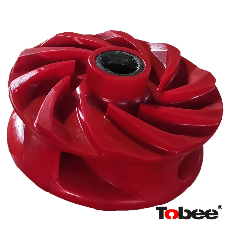
Previously we have discussed tip speed at some length, but to refresh you tip speed is simply the distance that any selected point on the peripheral of the impeller travels in a set time. In other words the “speed” of that point. To calculate tip speed you simply multiply the diameter of the impeller by pi (3.14159) which gives you the circumference of the impeller at the outermost tip. You then multiply by the rotational speed of the impeller (usually rpm, or rps) and this result is tip speed. The units for tip speed depend on the type of linear units and time units used, but when applied to impellers the common units are feet/min or meters/ sec. Having covered that, let’s look at how tip speed affects the pump’s head output. Those of us who suffered through physics in high school may remember the formula F = ma or force is equal to mass times acceleration. ( For everyone else, my congrats for avoiding hours of painful studying) This formula can also be applied to centrifugal pumps. Assuming that the mass of any given liquid passing through a pump will not change, the force ( pressure ) created will be solely as a result of the acceleration. When an impeller rotates within a centrifugal pump, the vanes accelerate the liquid down the vane providing the liquid mass with a velocity. The longer the vane (the radial distance from the beginning of the vane at the eye, to the outer end of the vane tip) and the faster the rotational speed, the more acceleration takes place producing a higher exit velocity of the liquid. Again for those physics people, rotational acceleration = velocity squared / radius Relating that back to a force (pressure) the illustration to the left shows how Since velocity equals radius times rotational speed we can substitute these two factors in place of velocity in the original force formula to create the formula below. F = M * R * 6.283 x 6.283 * n * n F = M * R * 39.48 * n * n Substituting diameter for the radius at R = 0.5D we then arrive at the, F = M * D * 19.74 * n * n Going back to our earlier statement that, for any given liquid passing through a pump the mass will not change, we can see that the only two factors that change to alter the force (pressure) are rotational speed and diameter. These are the same two factors that give us tip speed. While not exactly a direct relationship it does show that increasing tip speed increases head and that it can be done by either a rotational speed increase or a impeller diameter increase. I am sometimes asked if it is possible to estimate a pump’s head output when performance data or curves are not readily available, and the answer is yes. There is an old trick that will get you close to the rated head output. If you take the impeller diameter in inches and square that number, the result will be a close estimate of the pump’s shut-off head in feet when run at 1750 rpm. The estimate can be refined somewhat if you know the market the pump was designed for. High-efficiency water pumps use 1.1 times the impeller diameter and heavy slurry pumps use 0.9 times the impeller diameter. For example, we can use a Toyo DP-10 operating at 1750 rpm as a test case. Knowing it is a heavy-duty slurry pump, we would multiply the impeller diameter of 9.53 inches by 0.9 to obtain 8.58, squaring that number we obtain 73.5. A DP-10 has a shut-off point of approximately 70 ft, thus verifying our estimating formula . Note. For pump speeds other than 1750 rpm, use affinity laws to compensate accordingly.
In part 1 we discussed solids settling in a pipeline and how laminar and turbulent flow affect settling. It may have left you with the impression turbulent flow is always the way to go but it does come at a cost. Wear is increased and energy/ HP consumed and required pump output are both higher. (larger pumps) Today we will therefore look at types of slurries and how they react to flow rates below the velocities associated with turbulent flow. Given time any suspended solid with a specific gravity of greater than one will settle out. In a pipeline, however, the slurry is kept moving and if kept moving fast enough settling will not occur. A slurry that doesn’t settle at all at a given flow is said to be pseudo-homogeneous. The illustration below shows how the solids are equally dispersed across the whole pipe section. Although settling slurries in full turbulent flow can have even particle distribution across the pipe, the term pseudo-homogeneous is normally used in association with slurries in laminar flow. An example of just such a slurry is MFT (mature fine tailings) in the Alberta tar sands. When the particles within a slurry are fully suspended but not uniformly distributed (non-homogeneous) the slurry is said to be heterogeneous. This can occur in laminar flow when the velocity is close to the critical settling velocity but still sufficient to stop the formation of a” bed” in the pipe. (see below for info on “beds”) This is most often associated with transitional flow where the particles are settling quickly but turbulence close to the bottom of the pipe section constantly re-suspends the solids. In applications where the size and density of the solid is substantial heterogeneous flow is possible in full turbulent flow. When the particles are mostly suspended, a bed may form at the bottom of the pipe. If the particles continue to move (roll or sluff) it is said to be a moving bed application. This can occur in laminar flow when the velocity is close to, but not quite high enough to match the critical settling velocity. Transporting solids in this format requires a well-graded pipeline, as the solids will tend to sluff into low spots, possibly plugging the pipeline with little warning. When particles fall out of suspension, and form a bed that does not move, it is said to be a stationary bed application. This can occur in laminar flow when the velocity is below the critical settling velocity. Assuming this is a properly graded pipe and there is a fairly homogeneous slurry, stationary bed applications are quite viable and illustrations such as the one to the
Bookmark
Daniel Féau processes personal data in order to optimise communication with our sales leads, our future clients and our established clients.


This site is protected by reCAPTCHA and the Google Privacy Policy and Terms of Service apply.