


EUR
en
This Work Instruction will be as the guideline for Maintenance personnel to perform Limestone Slurry Pump Disassembly and Inspection.
This Work Instruction will be applied for Limestone Slurry Pump Disassembly and Inspection at Tanjung Jati B Power Plant. The works not mentioned in this instruction will be performed in accordance with drawings and appropriate specifications then will be considered to be added in this Work Instrcution later. This Work Instruction is refer to O&M manual from OEM.
The Maintenance Manager has responsibility for updating this instruction. The Maintenance Engineer has responsibility to control maintenance works made according to the instruction and co-ordinate with other teams during planning and report activities to the Maintenance Manager. The Maintenance Engineer and Supervisor have responsibility to plan, supervise and report of maintenance works which are undertaken in accordance with this procedure. The Maintenance Technician has responsibility to implement the Works Instruction in safe manner.
Work should be carried out by three people. Prepare all necessary drawings (part details drawing number D701471-15 R2, bearing assembly drawing number MK03506 and inspection report form (replacement parts record and vibration data record) prior to start of work. Prepare the necessary parts, tools and equipment before commencing actual work. Co-ordinate with Civil Section to provide access and lifting. Confirm that the equipment is isolated and a permit to work is available before commencing work. Prepare a suitable lay-down area. Remove the auxiliary piping, piping supports and all instruments that may interfere with the disassemble/reassemble procedures
Hand Gloves Safety Glasses Ear Plug or Ear Muff Welding Gloves Masker Full Body Hardness
WD 40 Cotton Rag Molykote Loctite 596 Dow Corning 111 Permatex Abrasives Paper Plastic Blanket Brush LPS G-49 degreaser Oil and Grease Wearing Compound
Detail List of spare parts use for Limestone Slurry Pump available on attachment 1.
Webbing sling length 4 meter end loop capacity 2 Ton, 1 set. Socket set: 14 mm, 17 mm, 19 mm, 24 mm, 27 mm, 30 mm, 36 mm. Combination spanner set: 14 mm, 17 mm, 19 mm, 24 mm, 27 mm, 30 mm, 36 mm. L-key 7 mm Adjustable wrench 36 inch. Pipe wrench (medium size), length 14 inch with 2 inch fitting capacity. Chain wrench rated pipe capacity 2 inch. Hammer, punch, screw driver set, measuring tape, ruler length 1000 mm.
Loosen and removal clamping bolts by socket and combination spanner 14 mm. Remove right side after loosen support bolts by socket and combination spanner 19 mm. Remove left side after loosen support bolts by socket and combination spanner 19 mm. Arrange the cover in the lay down area which prepare before. Clean the upper and lower cover. Loosen the adjuster bolts by adjustable wrench 36 inch to decrease belt drive tension. Remove belt drive and arrange in the lay down area which prepare before.
Loosen the three pulley bolts by combination spanner 19 mm and push the pulley out of the sheave. Loosen the sheave by inserting negative screw driver and pull out the sheave out of shaft. Remove the pulley as well after sheave removal. Arrange the pulley and sheave in the lay down area which prepare before. Clean the pulley and sheave by WD 40.
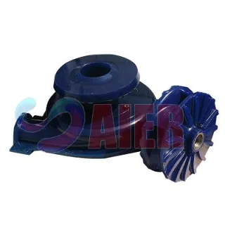
Removal suction pipe before suction casing by lossening and remove flange bolt use socket and combination spanner 27 mm and 30 mm. Arrange the suction pipe in the lay down area which prepare before. Loosen and remove the bolts NDE casing by socket and combination spanner 30 mm. Open and put the suction NDE casing in the lay down area which prepare before. Inspection and repair the rubber lining of suction casing.
Lock the impeller by pipe and rotate the shaft (reverse pump rotation) in the sheave position by chain wrench to unlock the impeller on the shaft. Loosen the impeller by hand, remove the impeller and put in the lay down area which prepare before. Inspection and repair the rubber lining of the impeller.
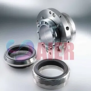
Loosen the static mechanical seal adjuster bolts by combination spanner 17 mm to make easier for access. Remove the mechanical seal rotating part from impeller side then put in the lay down area which prepare before. Loosen and removal clamping bolt mechanical seal static part by combination spanner 14 mm the continue removal mechanical seal static part after shaft (included in bearing chamber removal). Inspection, clean and lapping rotating and statics silicon carbide meeting face.
Bookmark
Daniel Féau processes personal data in order to optimise communication with our sales leads, our future clients and our established clients.


This site is protected by reCAPTCHA and the Google Privacy Policy and Terms of Service apply.