


EUR
en
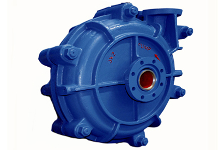
The Clarkson C-Valve is a throttling valve designed for slurry flow control. Though in some small sizes, the C-Valve will shut-off without damage, IT IS NOT A SHUT-OFF VALVE. Complete “bubble-tight” shutoff is not guaranteed. The valve has a cast ductile iron body which contains an elastomer muscle. The liner or sleeve is a molded elastomer part which is contained within the muscle. The sleeve is retained within the valve body with hard elastomeric retainers or, on the 6 inch and 8 inch sizes, with cast ductile iron retainer flanges. The C-Valve is available with a large selection of reduced port sleeve sizes and elastomers to fit many different applications.
The C-Valve is actuated by applying low pressure hydraulic fluid to the outer surface of the muscle. The muscle squeezes inwardly on the sleeve which forms a variable orifice. The normal operating range is from full open to ½ of wide open port diameter. The port will remain round and concentric up to this point. Valves with port diameters of 2 inches or smaller can be completely shut-off. The port closes out of round at shut-off. Since the hydraulic fluid is in contact with the elastomer muscle, care in fluid selection is important to assure maximum service compatibility. Fluid selection is discussed in Section 1.5 “Hydraulic fluid selection”. Actuators for the C-Valve are covered in Section 2 “Actuators”. See Section 3.4 Table 1 for closing pressures.
Normal maintenance of the C-Valve involves replacing the sleeve or the muscle. These will be covered separately but both require removing the C-Valve from the pipeline.
The C-Valve is usually installed with ASME B16.5 Class 150 standard pipe flanges using hex head cap screws. To insure complete sleeve support, use flat or raised faced companion flange with the contact surfaces that extend to the inside diameter of the C-Valve sleeve. The valve may be installed between concentric bell type reducers if the C-Valve is smaller than the pipeline. The use of flange gaskets is recommended on all C-Valves, but not required on NPS 4 and smaller valves. The valve should be located 5-10 pipe diameters away from any flow disturbance, other than concentric reducers. Install the C-Valve with the hydraulic connection on bottom of the body to facilitate purging the air from the valve top port. The piping used for the hydraulic fluid should be of adequate size to allow the valve to follow the control system with a minimal amount of lag time.
Sleeve replacement is the most common maintenance performed since this is the wear part in the slurry valve. It is performed as periodic maintenance, or due to failure. Failure is indicated by process fluid leaking from the weep holes in the end of the valve body near the pipeline flange connection. The sleeve replacement procedure follows:
The muscle usually lasts through several sleeve replacements. The failure mode is either rupture from over pressuring, or excessive swelling due to chemical attack from the hydraulic fluid. Muscle failure is indicated by hydraulic fluid escaping from the weep hole on the valve body near the pipeline flange connection or failure to fully open due to swelling. The muscle replacement procedure is as follows:
There are two different fluids recommended for use with the Clarkson C-Valve. For use with any unitized actuator we recommend a ‘Low silicate’ antifreeze without stop leak. This can be used concentrated as purchased or mixed with water to approximately 50%. This fluid is fully compatible with the elastomeric C-Valve muscle. • For actuation with a system using an electric hydraulic pump unit with a kindle pilot or electro-hydraulic control system, we recommend the use of turbine oil. Tests have shown that Chevron GST 32 turbine oil, Shell turbo oil #32, and Texaco Regal R&O 32 will minimize the swelling usually associated with the elastomer in contact with oil. Other acceptable turbine oils may exist, consult the factory for recommendations. Normal hydraulic oil is not recommended as the elastomer swelling may be rapid and significant causing valve operation problems. Swollen elastomer parts can cause valves to fail.
The simplest method of actuation for the C-Valve is by the use of a hand pump. The hand pump allows manual adjustment of the hydraulic pressure and therefore the C-Valve port size and slurry flow rate. The pump units available from the factory include a lever operated piston pump, pressure release valve, reservoir, hydraulic hose with female quick disconnect coupling, and pressure gauge. Several models are available with varying flow rates and reservoir capacities as required by different C-Valve sizes. These units can be left connected to a C-Valve for convenient flow adjustment or can be disconnected and moved from one C-Valve to another. See Table 1 for actuation pressures.
To adjust the flow through a C-Valve, connect the manual hand pump unit to the male quick disconnect fitting on the valve body and close the pressure release valve. Be sure the pump air vent screw on the fill cap is open before pumping fluid. Then pump until the desired hydraulic pressure is shown on the pressure gauge. At this time the pump can be left in place or can be uncoupled and moved to the next desired location. The check valve in the male fitting on the C-Valve will hold the pressure when disconnected. After removing the pump unit from the C-Valve, open the pressure release valve to drop the pump pressure. Reinstall the protective cover on the male coupling on the C-Valve. It is necessary to leave the pressure release valve open in order to reconnect the quick disconnect couplings.
Fill the reservoir with the appropriate hydraulic fluid and connect the coupling to the C-Valve to be operated. See Section 1.5 for ‘Hydraulic fluid selection’. Remove the protective cover from the male fitting on the C-Valve, and attach the female coupling on the pump unit hose to the C-Valve body. This is accomplished by opening the pressure release valve and sliding the knurled sleeve back on the female coupling. Then push the couplings together and release the sleeve. If desired, the couplings can be removed from the pump and C-Valve and the hose can be connected directly to the C-Valve port. Since the hydraulic fluid is subject to freezing (-30ºF and below), it is best to locate and store the pump inside a building, or to provide heating.
Maintenance of the manual hand pump unit is generally limited to keeping the unit clean and full of fluid. It is especially important to keep the coupling on the hydraulic hose clean. If the pump fails to pump fluid or maintain pressure, the piston and pressure release valve can be disassembled, cleaned and inspected. Insure all check balls, cavities and O-rings are in good condition. If not, repair or replace the defective parts.
The unitized actuator system has been designed for the Clarkson Series C-Valve to operate through its throttling range without need of an auxiliary hydraulic pressure source. The unit operates on up to 75 psig air supply and is controlled by a 3-15 psig pneumatic input signal. The actuator can be mounted directly on the valve or in a remote location. Unless otherwise specified, it will be shipped from the factory mounted on the valve and precharged with hydraulic fluid.
A pneumatic positioner controls the position of the unitized actuator piston assembly by following a 3-15 psig pneumatic input signal. The large area pneumatic piston is directly coupled to a smaller area hydraulic piston, so that the air pressure is amplified into a higher hydraulic pressure in the hydraulic end. The pressurized hydraulic fluid is displaced through a hydraulic hose into the C-Valve to attain the desired valve closure.
The main concern when installing the unitized actuator is to orient the vent port so that the air in the hydraulic system can be fully purged during charging. Allow access to the charging fitting on the valve body, as well as the positioner and I/P adjustments. The air supply should be filtered and regulated to insure the pneumatic positioner is protected from dirt and moisture. The filter bowl should be orientated so that the drain will function. These same requirements will be necessary whether the actuator is valve or remote mounted. The only other requirement for remote mounting is to allow all air to be purged from the hydraulic line connecting the valve body to the actuator by eliminating any ‘high spots’ in the line which cannot be vented. Whenever possible, the unitized actuator should be mounted above the level of the C-Valve body and the charging fitting on the valve body should be located at the lowest point. Since the hydraulic fluid is subject to freezing, it is best to locate the actuator inside a building, or to provide heating. The unitized actuator requires a maximum of 75 psi regulated, filtered air supply. The air supply is connected at the ¼ NPT port on the positioner. It is recommended that the air supply pressure be regulated to the lowest value necessary to actuate the valve. This air pressure can be noted on the air diaphragm pressure gauge, located on the positioner. For each C-Valve size, the hydraulic cylinder is sized to displace sufficient hydraulic fluid volume and pressure to obtain the maximum recommended closure. This requires that the range spring for the pneumatic positioner be matched to the proper valve / port size to insure correct actuator stroke.
The current to pressure transducer (I/P) used with the Clarkson C-Valves is the Conoflow Model GT18. The normal input is 4-20 mADC, which is converted into a 3-15 psig air signal. There are two adjustments which can be made: range and zero adjustment. The Moore products Model 73N12F direct acting and 73N12FR reverse acting positioners are used on the NPS 1 to 4 Clarkson C-Valves. Calibration of these positioners is limited to the range spring selection, and the zero adjustment.
It is sometimes necessary to mount the unitized actuator remotely from the C-Valve. This may be due to maintenance access, process considerations such as vibration, temperature, etc. Tubing between the actuator and the valve should be ⅜ I.D. or larger and provide air vents at any high spots. Trapped air and restricted flow will diminish the valve’s performance. When remote actuator mounting is desired the following suggestions will eliminate most potential problems: • If possible, mount the actuator higher than the C-Valve. • Mount the actuator with the vent port at the highest point in the system.
It may be necessary to rotate the C-Valve from horizontal to vertical pipeline mounting or the reverse. Consider the following suggestions: • The actuator fluid vent plug, located near the hydraulic hose, should be the high point in the system to facilitate charging with hydraulic fluid and complete venting of all trapped air. • The optional filter regulator should be positioned to allow any trapped airline moisture to be drained. • If the actuator vent hole is subject to a dirty environment, it may need to be protected. This can be accomplished by installing a breather/vent in the port and plugging the tapped holes. It is important not to plug the vent since venting is necessary. • The mounting between the actuator and the valve body is designed to allow installation with the fluid vent plug remaining at the highest point in the system regardless of pipeline orientation. The actuator will operate in any orientation, but it is recommended that the vent be on top to aid in recharging the hydraulic fluid. • The filter regulator will need to be re-tubed to accommodate its new position. Use only the comparable size and type tubing and fittings as were supplied with the original equipment. • It may be desirable to rotate the I/P converter, if provided. This will allow the electrical hook up, test, and adjustment points to be made more accessible. • If possible, make the hose or tubing-run with a continuous grade to eliminate air pockets. • If a continuous grade is impracticable, install vents at all air-trap points. • Install the C-Valve with the hose or tubing connected to the top port of the valve. • When charging the circuit, connect the charging pump to the bottom port of the C-Valve. • Open the vents in order of their location with the one nearest to the C-Valve first. • Pump fluid into the C-Valve until all air is purged from each vent and then close the vent(s). • Move to the next vent point and repeat charging step until all including the actuator vent are charged.
The unitized actuator system is made up of two major components: 1. The air over hydraulic actuator 2. The positioner The positioner used on 1 inch through 4 inch C-Valve actuators is the Moore products Model 73N12F direct acting or Model 73N12FR reverse acting, built-in positioner; and on the 6 inch and 8 inch C-Valve actuators the Model 74 side mount positioner is used. These positioners operate on a 3-15 psig air signal.
This procedure describes the disassembly and assembly of the NPS 1, 1.5, and 2 C-Valve actuator equipped with internal reservoir. The procedure is grouped into sub-assemblies to accommodate different assembly requirements. The fluid should be drained from the actuator prior to beginning this procedure.
Inspect all rubber components before starting to assemble components. Replace scratched or torn components. All hydraulic fluid should be drained prior to beginning this procedure.
Inspect all rubber components before starting to assemble components. Replace scratched or torn components.
In order to facilitate charging the C-Valve with unitized actuator, a low pressure hydraulic source is required. A hand pump with hose, fitting, and pressure gauge is available from the factory, but any pressure source properly cleaned and configured will work. The hydraulic source should include a pressure gauge (0-100 psi) and a short length of hose with a female quick disconnect fitting for connecting to C-Valve hydraulic fill port. All unitized actuators have vent ports in the hydraulic chamber. The valve body is supplied with a male quick disconnect fitting to allow charging. The other valve body port is connected to the unitized actuator by a flexible hydraulic hose.
The pneumatic hydraulic actuator (pilot) is a control device designed to supply regulated hydraulic pressure to the Clarkson C-Valve by following a 3-15 psig air control signal. This signal can be generated directly from a pneumatic controller, or manual loading station, or can be converted from a 4-20 mADC electrical signal using a current to pressure transducer (I/P).
The kindle pilot actuator multiplies the input air signal pressure change by a 20:1 ratio in the hydraulic output pressure. For example if the pneumatic control signal increases by 10 psig, (example from 4 to 14 psig), the output hydraulic pressure will increase approximately 20 times this amount or 200 psig. The pilot includes a “bias” air pressure regulator which can be used to set the instrument signal “zero point” anywhere between 0 and 15 psig. The normal purpose of this adjustment is to limit the hydraulic output pressure to the requirements of the particular C-Valve in use. This is accomplished by reducing the effective input signal pressure range and therefore the maximum output pressure. The hydraulic pressure source is normally provided by a separate electric hydraulic power unit such as the Clarkson 2GL unit.
The pilot is installed between the hydraulic pressure source and the C-Valve. It can be installed in any orientation. Its location should be fairly close to the C-Valve to minimize the pressure losses in the piping. Be sure to consider flow friction losses in designing the piping system layout and pipe size. If possible, the pilot should be located above the hydraulic pressure source, but below the C-Valve port with the pressure line connected to the lower C-Valve port, to aid in purging air from the hydraulic lines. Install isolation valves on both the inlet and outlet lines of the pilot. The system can be purged by removing the plug from the top port on the C-Valve, and pumping fluid through the circuit until all visible air bubbles stop. Since the hydraulic fluid is subject to freezing, it is best to locate the pilot inside a building, or to provide heating. All connections are made to the ¼ NPT pipe nipples on the outside of the kindle pilot enclosure. Air supplied to the pilot should be filtered to minimize the possibility of contamination. The pilot “bias” air regulator should be set to limit the maximum output pressure to the C-Valve to avoid damaging the valve’s muscle. See Table 1, Section 3.4 for actuation pressures. If the bias air is set above 3 psig the controller range or span can be adjusted to allow operation over the full control range.
This unit does not require regular maintenance. If the pilot acts “sticky” or stops maintaining proper output pressure, the hydraulic pilot valve may be clogged. It can sometimes be cleaned by removing the ⅞” hex plug from the bottom of the device. This should be done with the pressure from the hydraulic pressure source shut off. Then with the supply pressure valve from the hydraulic pressure source cracked opened, adjust the control signal up and down several times to flush out any foreign material. This is often sufficient to clean out any foreign materials and get the unit operating again. If this does not solve the problem, then the pilot may need to be repaired. Such repair should always include replacing all the rubber parts.
This system is designed to control the hydraulic pressure supplied to the C-Valve for slurry flow control. The system normally includes the following: • Pressure transducer which indicates the hydraulic pressure within the C-Valve body. • Three way dual coil closed center solenoid valve to adjust the hydraulic pressure to the C-Valve. • Flow control needle valve to modulate the oil flow to the C-Valve. • PLC to control the system (an existing DCS system can be programmed for this function if desired).
In operation, the customer supplied analog control signal of 4-20 mADC is input into the PLC. This signal value is compared to the analog feedback signal from the pressure transducer attached to the C-Valve hydraulic port. The PLC logic then energizes the appropriate coil on the dual coil solenoid valve, through built in relays, to adjust the pressure to the required value for flow control. An adjustable needle valve dampens the hydraulic fluid flow to allow smooth C-Valve pressure changes. A change in the control signal will cause the PLC to readjust the C-Valve to the new pressure. Also, drift in the feedback pressure will also cause the system to reset to the control point. On electrical power failure to the PLC or loss of either input signal, the C-Valve will lock in last position. If only the input or feedback signals are lost signal alarm relays will be energized. These relays are #5 for valve 1 and #6 for valve 2 on the PLC. The ‘electrical power loss-lock in last position’ included in the system is subject to drifting to open position with time. A true ‘hydraulic pressure loss-lock is last position’ could be installed as an option. The PLC supplied by the factory is a Modicon Micro. This unit can be pre-programmed to operate two separate C-Valves following two separate input control signals. Each C-Valve will require a separate three-way solenoid valve, transducer, and needle valve. A single model 2GL hydraulic power unit supplying 375 to 400 psig can be used to operate several separate C-Valve systems. The PLC can be programmed for either direct or reverse acting operation. Each different Clarkson C-Valve requires a unique maximum hydraulic pressure to obtain the allowable maximum throttling position without valve damage. This pressure value is set within the program in the PLC. The ability to adjust this set point is available for the PLC with an optional program called ‘modsoft’, or through an optional keypad interface available with the PLC.
The general arrangement of the components in this system is shown on the schematic drawing C6904. This drawing also shows how these components are interconnected. For details on installation of the 2GL HPU see the appropriate referenced drawings. Separate instructions are also available for the C-Valve. It is suggested that the pressure transducer and gauge be mounted and connected in close proximity to the C-Valve. The three-way control valve with the flow control valve can be mounted near the hydraulic pressure source.
The wiring required for the PLC with two C-Valves for this system involves the following basic steps.
The calibration of this system, assuming a fixed ratio pressure transducer, is accomplished by the PLC or DCS programmer. If a variable ratio pressure transducer is used, adjusting its setting can change the system control set point. If the optional ‘Key pad” is purchased with the PLC, some calibration adjustments can be input directly. The overall goal of any calibration is to allow the pressure to the C-Valve to range from zero to the maximum allowable pressure with an input signal varying from 4-20 mADC.
The following recommendations will help in maintaining the C-Valve. • Keep the outside of the valve clean so that gauges can be read and filter/ breathers are clear. • Inspect regularly for leakage of air, hydraulic fluid, or slurry. Locate the source and correct any leak immediately. • Keep all gauges in working condition. Troubleshooting and calibration require accurate measurement of air supply, instrument, air diaphragm, and hydraulic pressure. • Because the C-Valve sleeve is a replaceable wear part, it is recommended that a maintenance log be used to record sleeve life. This information can be used to schedule sleeve replacement and stock spare parts. • Do not use the C-Valve as an isolation valve or leave in the fully closed position for long periods.
The following flowchart can be used to troubleshoot a problem with a C-Valve equipped with a unitized actuator.
The following is a partial list of possible system problems and likely solutions. This is based on using the Modicon 612 PLC.
The maximum hydraulic pressure values in the above Table 1 are based on closing the C-Valve to 50% of the full open port diameter for sleeves with port diameters greater than 2 inches. All values assume the valve ends are flanged. The pressure values for sleeves with port diameters smaller than 2 inches are based on visual closure. All these values are approximate and intended as a guideline only. Values will vary with different sleeve and muscle material selections.
Bookmark
Daniel Féau processes personal data in order to optimise communication with our sales leads, our future clients and our established clients.


This site is protected by reCAPTCHA and the Google Privacy Policy and Terms of Service apply.