


EUR
en
A stainless steel (SS) three belt, belt filter press shall be utilized to dewater the sludge produced by the plant. The sludge feed pumping system, polymer feed system, sludge conditioning system, and dewatered cake discharge pumping system shall be integrated into the belt press system and be supplied by a single supplier.
These specifications encompass equipment that pre-thickens and presses sludge into a pressed filter cake for disposal. Rotary drum thickeners, a sludge press and the accompanying electrical controls shall be included. Four distinct belts of the same material and porosity shall be used. The first belt is on the Rotary Drum Thickeners (RDT). They perform the initial solid/liquid separation by utilizing a screw filter drum to convey the sludge while allowing free water to drain through the belt. The second belt is a single seamless belt that conveys the thickened sludge via a gravity thickening zone to the press zone. The press zone consists of the third belt wrapped around a stainless steel perforated cylinder which the seamless belt presses against to accomplish final dewatering. The structure of the press shall allow for filtrate collection and discharge from a two 6” connections. All stainless steel shall be 304 unless otherwise noted.
These specifications describe an integrated system with equipment furnished by Aero-Mod, Inc. For this application, one (1) Model 1500 Series Tritan™ 1.5 m belt filter press, or equal, shall be used.
To be considered, the supplier must have a minimum of 20 U.S. installations having been in operation for a period of 5 years or more that meets the technical specification set forth below.
Affixed to the top of the belt filter press shall be two RDTs. Each of the RDT’s shall be installed in a SS enclosure that encloses two motor driven Archimedean screw filter drums covered with woven polyester cloth. Conditioned sludge shall enter the RDTs and be conveyed to the outlet chute while the free water is allowed to drain through the polyester-covered Archimedean screw into the filtrate collection tank. The RDTs shall have a drum washing mechanism inside the tank for maintaining the porosity of the polyester cloth.
A stainless steel enclosure shall be provided to collect the filtrate from the Archimedean screw filter drums. The enclosure shall have access doors from the top. Two 4” diameter inlet flanges are used to feed conditioned sludge into the RDT enclosure. The filtrate from the enclosure shall drain via the structural members of the press to the filtrate collection pan.
The screw filter drums shall be a stainless steel Archimedean screw and shall have a diameter of 1.97 feet (23.62 inches) covered with a polyester filter belt (first belt) fixed to them.
Each Archimedean screw filter drum shall each be turned by a SEW Eurodrive 1.0 HP, 3 phase, 230/460V worm geared motor. The speed shall be variable from 4.6 to 27.4 rpm. The motor shall mount directly to the shaft of each filter drum. Asensor shall be provided to monitor the rotation of each screw filter drum for alarm and/or shut down conditions.
The RDTs shall each be provided with a filter drum wash water manifold pipe fitted with polypropylene jet spray nozzles accessible via the enclosure doors. The manifold pipes shall be stainless steel.
The enclosure shall have an outlet chute at the discharge end of the RDT’s to allow the pre-thickened sludge to fall by gravity onto the gravity thickening zone of the belt filter press.
Located under the RDT enclosure shall be the sludge pressing section. This section shall consist of the gravity thickening zone followed by the press zone made up of a seamless belt (second belt), a belt-covered perforated cylinder (third belt), a belt transmission system, a belt tensioning system, a belt washing system, an automatic belt alignment system and a filtrate collection tank.
This will consist of the seamless belt rising at an angle and utilizing five adjustable baffles. The baffles are of stainless steel. The height adjustment of the baffles will utilize nylon plastic bolts. Two of the baffles shall have attached to them multiple nylon plastic bolts to create a “comb” to further enhance the thickening and spreading of the sludge.
The seamless belt shall be 1.7 meters wide and have a “zig zag” seam to reduce any stress points that could exist from tensioning. Another belt of the same material shall cover a stainless steel perforated cylinder. The press zone is where the two belts meet prior to final discharge.
The belt transmission system shall be made up of: - Three (3) 0.20 ft. diameter SS belt support bars. - Four (4) 0.55 ft. diameter cloth transmission rollers. - One (1) 0.90 ft. diameter belt tensioning roller - One (1) 1.97 ft. diameter perforated pressing cylinder
All bearings shall be stainless steel bearings type SHCR (stainless steel housing with corrosion resistant insert).
The belt transmission shall be driven by a 0.5 HP, 230/460V, 3 phase motor capable of varying speeds up to 2.8 rpm.
Washing mechanisms shall be provided for the belt-covered perforated cylinder and the seamless belt. Factory installed SS pipe and SS flex hose are used to feed water to the washing mechanisms. The frame of the washing mechanisms shall be constructed of stainless steel.
This washing mechanism shall consist of a SS manifold with polypropylene jet spray nozzles that wash the belt filter cloth which covers the perforated cylinder. This spray wash bar is housed in a neoprene rubber shroud.
This water washing mechanism shall consist of a SS manifold with polypropylene jet spray nozzles to clean the seamless belt filter cloth. This manifold will be covered by a SS removable hood with neoprene rubber siding.
The belt alignment/air pressure assembly shall consist of: - Two (2) Proximity Sensors to serve alignment and alarm functions - One (1) Solenoid Alignment Valve - Two (2) air regulators with gauges - One (1) pneumatic cylinder. - Two (2) pneumatic actuators for belt tensioning. - A high-pressure air source (90-psi min.) must be is required to operate the alignment system
The high pressure system must have the capacity to provide 5.5 cf of air on initial start-up of the press. A storage tank of at least 30 gallon capacity must be provided. It is recommended a duplex compressor system is provided that will supply high pressure air to the storage tank. Each compressor shall have the capacity to produce at least 1 cfm at 100 psi. See Section 6.0 Air Compressor.
A filtrate collection pan shall be integral with the press. It will be located below the belt press assembly. The pan shall be constructed of stainless steel and will include two 6” filtrate discharge pipes for connection.
The sludge discharge shall consist of a weighted doctor blade fabricated of high-density polyethylene.
A 3.0 HP, 230/460V, 3 phase centrifugal booster pump shall be provided to supply high-pressure water for washing purposes. A water tap (1½” N.P.T.) into the unit shall be provided on the centrifugal pump for a 1½” solenoid valve with unions (1½” N.P.T.) for hard piping hookup. This feed line shall have a pressure sensor used to shut down the press should water pressure be lost. Potable or Filtered Non-Potable wash water at a minimum rate of 50 gpm (50 psi) is required.
Two (2) NEMA 4X stainless steel panels shall be factory mounted and pre-wired on the belt filter press. One panel will be the main power panel and the other the PLC control panel. Contractor shall only need to connect power to the high voltage panel and Ethernet communication to the low voltage panel.
This panel shall receive 24VDC power from the main power panel. It shall utilize an Allen-Bradley Compact Logix Platform PLC with an Allen Bradley 6” color OIT (touch screen) with VNC capability . The panel shall be fitted with alarm lamps and power on light. Pilot lights shall be full voltage LED type for long life. Control of the belt alignment system will be included in this panel. Emergency shutdown of the entire belt press system including the RDTs and belt filter press shall be from this panel . It will indicate alarm conditions for the press as well as the associated equipment tied to this panel which can include the sludge feed pump, the sludge cake discharge system and the polymer/sludge conditioning system. This panel shall be composed of fuses, remote switches and thermal relays. Asingle dry contact shall be used for alarm purposes for the entire system including ancillary equipment. The control panel shall have the following control functions: 1) Control the sludge feed pump speed; display the current sludge feed rate in gallons per minute and the total flow of feed sludge in gallons. 2) Turn on/off the sludge cake discharge system. 3) Control the polymer pump speed and display the current polymer feed rate in gallons per hour and the total flow of polymer in gallons. 4) Display both RDT RPMs 5) Provide automatic belt press shutdown consisting of: a. Turning off the sludge pump system b. Turning off the polymer/sludge conditioning system c. Delay of starting final wash down cycle to allow the sludge on the press to exit the machine. d. Start and operate the final wash down cycle. e. Turn off the sludge cake system by either a proximity sensor and timer shutting down the cake pump or when the press shuts down the cake pump does as well. f. Turn off the belt press system, water booster pump, and releases the pneumatic pressure. 6) Automatic belt press shutdown can be programmed for a set time of day 7) The OIT shall display operational events and alarms Communication from the this panel to sludge feed pump, polymer system, and/or cake conveying/pump system shall be by Ethernet IP (CAT 5e minimum).
The main power panel shall contain Allen Bradley Powerflex 525 variable frequency drives for the RDT motors and belt press motor. The MCP for the booster pump motor will be included in this panel. A 480/24VDC power supply unit will be factory installed in this panel. Fuses and 3 phase surge protection are included with the panel.
The following information is a summary of the requirements needed for installation and operation of the belt filter press. Please note these requirements do not include any requirements for the ancillary equipment. The following utilities must be supplied by the user.
The belt filter press requires a 230/460V, 3 phase 30 A service. Wiring cannot extend over 100 feet from the power source without voltage drop.
The belt filter press shall have a 1.5” N.P.T. connection at the booster pump. Aconstant supply of 50-60 gpm at the inlet to the pump is required.
An 8” floor drain is required for removal of the filtrate from the dewatering area.
The equipment covered by these Specifications shall be of standard units of proven ability as manufactured by reputable concerns having long experience in the production of such equipment. The equipment furnished shall be designed, constructed, and installed in accordance with the best practice and methods, and shall operate satisfactorily when installed as shown on the Drawings.
All equipment shall be designed and built for 24-hour continuous service at any and all points within the specified range of operation, without overheating, without cavitation, and without excessive vibration or strain.
The pumping units required under this section shall be complete. All parts shall be so designed and proportioned as to have liberal strength, stability, and stiffness and to be especially adapted for the service to be performed. Ample room for inspection, repairs and adjustment shall be provided.
Stainless steel nameplates giving the name of the MANUFACTURER, the pump serial number and material code and all other pertinent data shall be attached to each pump, motor, and control panel.
All working parts of the pumps and motors, such as bearings, wearing rings, shaft, sleeves, etc., shall be standard dimensions built to limit gauges or formed to templates, such that parts will be interchangeable between like units and such that the OWNER may, at any time in the future, obtain replacement and repair parts for those furnished in the original machines.
The nameplate ratings of the motors shall not be exceeded, nor shall the design service factor be reduced when the pump is operating at any point on its characteristic curve at maximum speed.
Mechanical equipment, including drives and electric motors shall be supplied and installed in accordance with applicable OSHA regulations. The noise level of motors, unless otherwise noted, shall not exceed 85 dBA measured 3 meters from the unit under free field conditions while operating on utility power.
All lubrication fittings shall be brought to the outside of all equipment so that they are readily accessible from the outside without the necessity of removing covers, plates, housings, or guards.
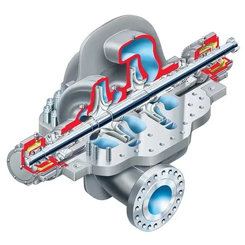
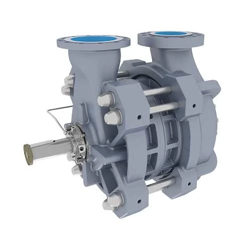
System and fluid conditions Fluid (name) BFP Feed DS content (%) 1-2% Temp. (°F) ambient pH value approx. neutral Specific Gravity Capacity (gpm) 60-200 gpm Suction condition flooded Pressure (psi) 30 psi Duty (hrs/day) constant Pump unit Model BOERGER PL 300 (or equivalent) Drive Type geared motor Drive Arrangement in-line Motor Power (HP) 5.0 HP Pump speed (60 Hz) 275 rpm Suction Flange 4”ANSI 150 lbs Discharge Flange 4”ANSI 150 lbs
The static mixer is to be connected to the outlet header directly following the polymer injection point. The static mixer shall have a 6” threaded clean out cap for removal of the internal baffles for cleaning. The static mixer shall be manufactured of 6” Scheduled 80 PVC pipe with stainless steel internal baffles and shall be 55 ½” long. A special 6” box end wrench shall be supplied by the manufacturer.
Above the sludge pump shall be inlet and outlet headers to enable the pumping of the sludge from the sludge withdrawal point to the dewatering equipment. The inlet and outlet header shall be made of 4” Scheduled 80 PVC piping.
A NEMA 4X fiberglass panel shall be mounted on the aluminum stand and shall supply power to the sludge pump and will consist of the appropriate contacts, variable frequency drive and switches. A transformer shall be supplied within the sludge pump panel to step down the incoming power to 115 Volts to operate relays and control functions of the variable frequency drive for the sludge pump. The control panel face shall have the following:
Control wiring from the belt press panel to this sludge feed pump panel will be required in the field.
The polymer dilution blending and feeding unit should include all drives, motors, valves, piping, supports, controls, and accessories necessary for a complete and operable system. Each system shall be completely piped, wired and tested before shipment.
The liquid polymer preparation system shall be capable of metering precise amounts of liquid polymer and water and subsequently processing the mixture to provide a fully activated polymer solution. All components of the system shall be installed on a single stainless steel skid. The control panel, rotameter, mixing motor, activation chamber and other system components shall be factory installed on the upper base plate. The neat polymer pump shall be factory installed to the lower base plate.
This section specifies a metering pump, complete with an electric motor, and all specified appurtenances, as shown on the plans and specified herein.
The pumping unit shall be of the electronic solenoid-driven diaphragm type designed for pumping liquid polymers.
The pump shall have the following operating characteristics: 1. Flow Range – 0.06 to 4.5 gph 2. Max Working Pressure – 175 psi 3. Discharge Connection – ½” Male NPT
The progressive cavity chemical feed pump shall be Chem-Pro C2 Series, as manufactured by Blue-White Industries, or LMI series B, or equal.
This section specifies the activated polymer feed system and all specified appurtenances.
The polymer preparation system shall be an Acrison, Inc. Model 580-1 .
The liquid polymer preparation system shall include a pressure reducing valve, rotameter, flow-adjusting valve and solenoid valve, for control of dilution water. The rotameter and manual flow adjusting valve shall be front panel mounted. All components shall be pre-piped at the factory.
Primary activation shall be in a high intensity chamber constructed of a clear synthetic material. Liquid polymer is to be metered directly into the Dispersion-Injector, where the polymer disperses into a fine cylindrical stream while simultaneously mixing with high intensity flowing water. The output solution from the Dispersion-Injector discharges into an Activation Chamber where final and complete polymer activation instantaneously occurs. The Dispersion-Injector shall utilize a highly efficient and reliable technique to first disperse and then mix liquid polymer with water; it alone shall produce a near-perfect solution. Its design shall not include any components anywhere within the liquid polymer supply line, and all of its internal areas shall be continuously flushed with rapidly flowing water. The Dispersion-Injector shall contain and isolate the liquid polymer whenever the metering pump is not operating or the Processing Module itself is shut-off.
Shall be a constant speed motor-driven activation chamber designed to ensure complete polymer activation without allowing incompletely processed polymer to short circuit the system, or allow activated polymer to recirculate within the system. The activation chamber shall be self-cleaning and constructed of 316 stainless steel and clean synthetic material, allowing visual usual observation of internal operations, rated at 100 PSI and a direct coupled, 1/2 HP, TE motor with manually resettable overload protection. The activation chamber shall be specifically designed to provide two distinct energy zones, a centrifugal blending zone and a controlled shear zone to mix the polymer and water for complete, positive polymer activation without recirculation or short circuiting.
A differential pressure switch shall be included within the system and wired to the control panel to automatically de-energize the system should a backflow condition occur.
Pressure gauges shall be included for both inlet and discharge pressure readings.
A floor stand shall be provided to elevate the unit to a convenient height. The floor stand shall be constructed of 304 stainless steel.
A NEMA 4X control panel shall be factory mounted and wired as an integral part of the system. The control panel shall include: 1. Local/Off/Remote (HOA) stop-start control for the system 2. Off/Remote stop-start control for the polymer pump 3. In the event of a low differential pressure condition, logic shall be provided to allow the operator to select either a pause in pump operation or a complete system shutdown requiring a re-start to resume operation. 4. Separate dry contact outputs shall be provided to indicate system operating and general alarm. 5. Indicator lights shall be provided for power on as well as an alarm condition. The alarm circuitry shall include low differential pressure and activation chamber overload. 6. The panel shall utilize 115 volt, 60 Hertz, single phase power. 7. Communication with Belt Filter Press PLC shall be by Ethernet IP. Control wiring from the belt press panel to this polymer feed and mixing system will be required in the field.
The equipment covered by these Specifications shall be of standard units of proven ability as manufactured by reputable concerns having long experience in the production of such equipment. The equipment furnished shall be designed, constructed, and installed in accordance with the best practice and methods, and shall operate satisfactorily when installed as shown on the Drawings.
All equipment shall be designed and built for 24-hour continuous service at any and all points within the specified range of operation, without overheating, without cavitation, and without excessive vibration or strain.
The pumping units required under this section shall be complete. All parts shall be so designed and proportioned as to have liberal strength, stability, and stiffness and to be especially adapted for the service to be performed. Ample room for inspection, repairs and adjustment shall be provided.
Stainless steel nameplates giving the name of the MANUFACTURER, the pump serial number and material code and all other pertinent data shall be attached to each pump, motor, and control panel.
All working parts of the pumps and motors, such as bearings, wearing rings, shaft, sleeves, etc., shall be standard dimensions built to limit gauges or formed to templates, such that parts will be interchangeable between like units and such that the OWNER may, at any time in the future, obtain replacement and repair parts for those furnished in the original machines.
The nameplate ratings of the motors shall not be exceeded, nor shall the design service factor be reduced when the pump is operating at any point on its characteristic curve at maximum speed.
Mechanical equipment, including drives and electric motors shall be supplied and installed in accordance with applicable OSHA regulations. The noise level of motors, unless otherwise noted, shall not exceed 85 dBA measured 3 meters from the unit under free field conditions while operating on utility power.
All lubrication fitting shall be brought to the outside of all equipment so that they are readily accessible from the outside without the necessity of removing covers, plates, housings, or guards.
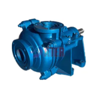
Fluid Name Sludge Solids Content 13-16% Capacity 10 GPM Discharge Pressure 60 psi Suction Condition Flooded Temperature Ambient pH Value 7 Specific Gravity 1.0 Duty Inter
Model PL 200 Drive Type Nord SK 22 Drive Configuration Inline Motor Power 5 HP Pump Speed 80-270 rpm Suction Flange 4” ANSI 150-lb Discharge Flange 4” ANSI 150-lb
Open Hopper 1321 mm x 430 mm Drive Type Nord 100 LR/4 Motor Power 5 HP Feed Screw Speed 63 rpm
The auger unit shall be driven by a parallel shaft gear reducer and 4-pole electric motor.
The motor shall be 3-phase, 60 Hz, 460 V, with1.15 service factor and class F insulation.
Gear reducer shall be flange mounted to the auger unit and shall support the feed screw shaft.
Each pump shall include a gear reducer and 1800 rpm electric motor.
All motors shall be built in accordance with latest NEMA, IEEE, ANSI and AFBMA standards where applicable.
A Puma, or equal, 3.0 HP, 230/460 V/3 ph air compressor with an 80 gallon vertical air tank, pressure switch, and oil particulate
Bookmark
Daniel Féau processes personal data in order to optimise communication with our sales leads, our future clients and our established clients.


This site is protected by reCAPTCHA and the Google Privacy Policy and Terms of Service apply.