


EUR
en
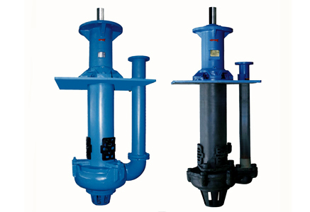
Close-coupled pumps are assembled into a rigid unit which requires a minimum of preparation for mounting. this type of pump should be bolted down securely; otherwise, it may shift its position enough to cause the pump case to crack. The close-coupled pump can be mounted in any position. However, when the pump is mounted in other than a horizontal position, the pump motor must be located above the pump so that if leak age should occur, the dripping liquid will not enter and possibly damage the motor. Pumps which are close-coupled to engines must be mounted horizontally, because the engine’s fuel and lubricating systems will not function properly in any other position.
It is absolutely necessary to provide a perfectly flat, horizontal mounting surface. Where such a surface exists, it should be possible to achieve final adjustment by bolting the base plate directly to this surface and using shims under pump or motor to correct any misalignment. A pump foundation must be constructed when a flat mounting surface does not exist. ln addition to providing a substantial mounting surface, the foundation, when designed to elevate the pumping unit above floor level, may be helpful in protecting pump and driver from flooding and from alignment-destroying jolts by hand, trucks, etc., and also helps to minimize vibration. A concrete foundation should be poured after base- plate bolts have been accurately located. Bolts should be inserted in pipes or sleeves having diameter 2 or 2 1/2 times as large as the bolt diameter. These sleeves will permit slight adjustment of bolts to compensate for inaccuracies in location of bolts or base-plate holes. Anchor the bolts at the lower end of sleeves by means of large washers. The foundation should be sturdy enough to support the weight of the pump without deflection or vibration and large enough to ex ceed the length and width dimensions of the base plate by 3 or 4 inches. The top surface should be fairly rough and irregular, so that grout will adhere to it properly. Set pumping unit on unfinished foundation, using metal shims having a total thickness of 1 to 1-1/2 inches under the edge of the base near each foundation bolt. Bases which are long and narrow should be supported by additional shim stacks and anchors at the mid-point. Wedges should be leveled so the base clears the foundation by 3/4 to 1 inch.
Never allow pump to carry weight of piping. Both suction and discharge piping should be supported independently at a point near the pump. Piping must be installed carefully so that it will not be necessary to force it into place when connecting to the pump. In unusually long discharge lines, and in lines which are subject to wide temperature ranges, expansion joints or other flexible connectors should be used to compensate for elongation of the pipe due to pressure or temperature. Flexible connectors also are helpful as a means of preventing transmission of noise and vibration. Consult tables showing friction losses in pipe when selecting pipe sizes.
The pump should be installed as close to the source of liquid as possible. When high suction lifts (15 feet or more), hot liquids, or intricate suction piping is involved, a careful check must be made to be sure that the pump’s required net-positive suction head (NPSH) will be met. The suction line should be short, simple and the largest diameter as practical; it should be placed so that it rises gradually toward the pump and in such a way that the pump suction is at the highest point in the suction line. Use as few fittings as possible and utilize smooth, long-radius fittings where space permits. Avoid attaching an elbow directly to the pump suction; use a length of straight pipe or an eccentric reducer to provide proper entry of liquid into pump. Do not use throttling valves or orifices in the suction lin e. These may cause cavitation which can seriously damage the pump. These instructions have been provided so that the user can derive the optimum performance from his centrifugal pumps. Particular attention must be paid to the instructions pertaining to piping, so that the pump will be able to perform the job for which it was selected. Faulty installation may not only prevent the pump from functioning properly, but also may cause serious damage.
Discharge piping is not as critical as suction piping, but care should be exercised in sizing and laying pipe in order to avoid unnecessary frictional losses. As in suction piping, the number of fittings should be minimized and abrupt changes in direction and size of piping should be avoided. A gate valve should be installed in the discharge line; it will be of assistance when priming the pump and will permit service to be performed on the pump without needing to drain the discharge line and any connected vessels. It is advisable to install a check valve in the discharge line between the pump and gate valve in a system operating at high discharge heads and with a foot valve on the suction line. The check valve protects the pump from pressure surges which occur when the pump is stopped. In pressure systems without a foot valve, the check valve prevents reverse rotation of the pump and loss of pressure in the discharge line if the pump stops. For systems with very high discharge heads (above 80 psi), a non-slam check valve should be used.
Large E, F & G series pumps, whether equipped with packing or a mechanical seal, are provided with a recirculation line which allows high pressure fluid from the pump volute to flow to the seal chamber. This introduction of higher pressure liquid into the seal chamber acts as a seal, preventing air from leaking into the pump when suction pressure is below atmospheric pressure. To prevent damage to the recirculation line during shipment of the pump, the pump is usually shipped loosely. All necessary fittings are attached to the line. Merely insert the line into the tapped openings in the volute and seal chamber and tighten the fittings. If the pump is being used in a system that exerts substantial positive pressure (more than 10 psi) on the pump suction, it may be advisable to substitute a longer recirculation line which will connect the seal chamber to the pump inlet. This substitu tion will permit seal chamber pressure to be approximately equal to suction pressure and thus reduce the amount of pressure, which must be withstood by the packing or mechanical seal.
Larger single-phase motors (either close-coupled or general purpose) and all three-phase motors must be provided with a manual starter which incorporates overload protection. For overload protection as well as automatic operation (in conjunction with a float or pressure switch), a magnetic starter must be used. Electric wiring to the. motor should be sized in accordance with applicable codes or handbooks. Undersized wires will cause a voltage drop which may result in damage to the motor. Be certain the current characteristics of the electrical are in agreement with those required by the motor. Verify desired voltage by checking the instructions for connecting the motor leads of a dual voltage that appear in the cover of the motor conduit box.
If there is any possibility that a pumping system will allow the pump to run dry (loss of prime, empty tank, etc.) the pump must be protected by an automatic control. Contact the factory for assistance in selecting loss-of-prime switches, low- liquid-level shut-off controls, etc.
Centrifugal pumps (except self-priming models) must be primed (filled with liquid) before pumping starts. For pumping systems which have a foot valve on the end of the suction line, the easiest way to prime the pump is to fill suction line and pump enough of the discharge system to establish a liquid level 1 or 2 feet above the top of the pump case. Any air trapped in the pump case should be allowed to escape by removing the top plug until a steady stream of liquid flows from the opening. Turn the pump shaft by hand to allow any air trapped within the impeller to escape. Wait several minutes for air to escape from any horizontal runs of suction pipe. Replace plug and prepare to the start pump.
Correct direction of rotation is assured when pump is furnished complete with single-phase motor. These drivers are selected to impart correct rotation to pump. It is very important, however, to check for correct rotation when three-phase motors are furnished, or when drivers of any type are supplied by others. Check rotation of three-phase motors by turning on power for only an instant allowing the pump to turn a few revolutions. Be aware that prolonged operation of pump in the wrong direction may damage it! Note whether shaft rotation is in agreement with directional arrow on pump case. If direction is wrong, obtain opposite rotation by interchanging any two of the three wires either at the motor or starter. Close gate valve in discharge line and start pump. Open valve gradually to a half-open position once driver attains operating speed. If pump fails to function after a few seconds of operation, stop it and allow it to remain idle for several minutes. Add more priming liquid if needed and open air vent (or remove top plug) briefly to permit any accumulated air to escape. Re-start pump; if the pump still fails to function, stop it and repeat priming and air-bleeding procedure. If repeated attempts at starting the pump are unsuccessful, check for leaks in foot valve, suction piping or pump stuffing box. Do not permit pump to run for more than a few seconds unless it remains full of liquid and is discharging properly; prolonged operation of an unprimed pump can cause severe damage to rotating parts. A discharge pressure gauge, mounted at the pump discharge will indicate the pressure being developed by the pump, thereby determining whether the pump is operating properly. When proper pump operation is obtained and if the discharge line remains full at all times, the discharge gate-valve can be opened fully and allowed to remain open until the pump must be serviced or reprimed. For pumping systems which are especially large or which do not incorporate a foot valve, and yet must be primed in order to overcome a suction lift condition, other methods of priming are available. Hand-operated or motor (engine) driven vacuum pumps can be used to evacuate air from pump case and suction piping; the vacuum pump must be capable of lifting the priming liquid to a level above the pump case and within a reasonable len gth of time. The discharge line must have a check or gate valve located near the pump in order to limit the volume of air to be removed. Pumps equipped with a stuffing box should be checked for proper adjustment. This adjustment must be made while pump is running; gland should be tightened so that a very slight leakage (6-10 drops per minute remains). This leakage lubricates the packing and helps prevent excessive wear on shaft, or shaft sleeve and packing. Pumps furnished with mechanical shaft seals require no adjustment. If the pump must be shut down after initial startup, due to exposure to below freezing weather, protect the pump and connected piping from damage by draining the system completely or by introducing a corrosion-inhibiting anti-freeze into the system.
The rotating parts of the centrifugal pump (impeller, shaft, seal elements, etc.) are lubricated by the liquid being pumped. No additional lubrication is required. DO NOT START OR RUN PUMP DRY.
PACKED PUMPS, or pumps with packed stuffing box, should be adjusted when leakage becomes excessive by tightening the packing gland nuts evenly. Never tighten so severely that the leakage through the pac king is stopped entirely. Always have the pump running while making this adjustment. When leakage cannot be controlled by additional tightening, remove packing gland and add one ring of pac king, replace gland and make final adjustments while pump is running. When packing has been added in this manner once or twice, it is advisable to remove all packing the next time that service is required. T o remove old packing either loosen gland and run pump briefly allowing the pump pressure to force the packing rings out or use packing removal tools. Add four rings of new packing so that the ring butt joints are 180 degrees from each other. This type of packing, suitable for temperatures up to 200°F is available in ring form (six rings per set) from the factory. We also can furni sh specia l packing (su ch as T eflon, etc.) for use in pumps which are handling solvents and corrosive liquids. The useful life of pump packing is shortened considerably when the shaft sleeve is worn. It should be inspected and replaced, if necessary.
Sea adjustments are not required; the seal is lubricated by the liquid being pumped (unless a special provision has been made for an external supply of cool or clean water to the seal). Occasionally, a new seal may leak slightly during its first hour of operation, but unless the seal is faulty or the installation has been done incorrectly, this leakage will stop. When leakage occ urs after the pump has been used for a long time, a seal must be replaced. The shaft seal for pump service is a precision product which must be handled with care. Do not drop the brittle carbon-sealing washer or seat face, and do not scratch their lapped surfaces. Damage and consequent seal malfunction are almost certain to occur if these parts are mishandled. The pump case, impeller and bracket must be removed from driver or frame mounted unit in order to replace the shaft seal. Complete instructions for dismantling pump and removing impeller can be found in applicable paragraphs below.
Bookmark
Daniel Féau processes personal data in order to optimise communication with our sales leads, our future clients and our established clients.


This site is protected by reCAPTCHA and the Google Privacy Policy and Terms of Service apply.