


EUR
en
Multistage pump is a kind of centrifugal pump, which is a collection of two or more centrifugal pumps with the same function. In the structure of the fluid channel, the medium pressure relief port of the first stage is communicated with the inlet of the second stage. The medium pressure relief port of the second stage is communicated with the inlet of the third stage, and this series of mechanisms forms a multi-stage centrifugal pump.
Single-stage pump refers to a pump with only one impeller, and the highest head is only 125 meters; while multi-stage pump refers to a pump with two or more impellers.
There are many series of multistage pumps, which are divided into vertical multistage pumps and horizontal multistage pumps according to their appearance. According to different materials, it is divided into: stainless steel multistage pump, lg multistage pump, da multistage pump.
Multistage pumps can be used in many industrial sectors such as petroleum, chemical, machinery, mining, light industry, medicine and food. In many technological processes of industrial production, such as vacuum filtration, vacuum water diversion, vacuum feeding, vacuum evaporation, vacuum concentration, vacuum resuspension and vacuum degassing, multi-stage pumps are widely used. It can pump out flammable and explosive gases, and also pump out dusty and water-containing gases. Therefore, the application of water ring pumps is increasing.
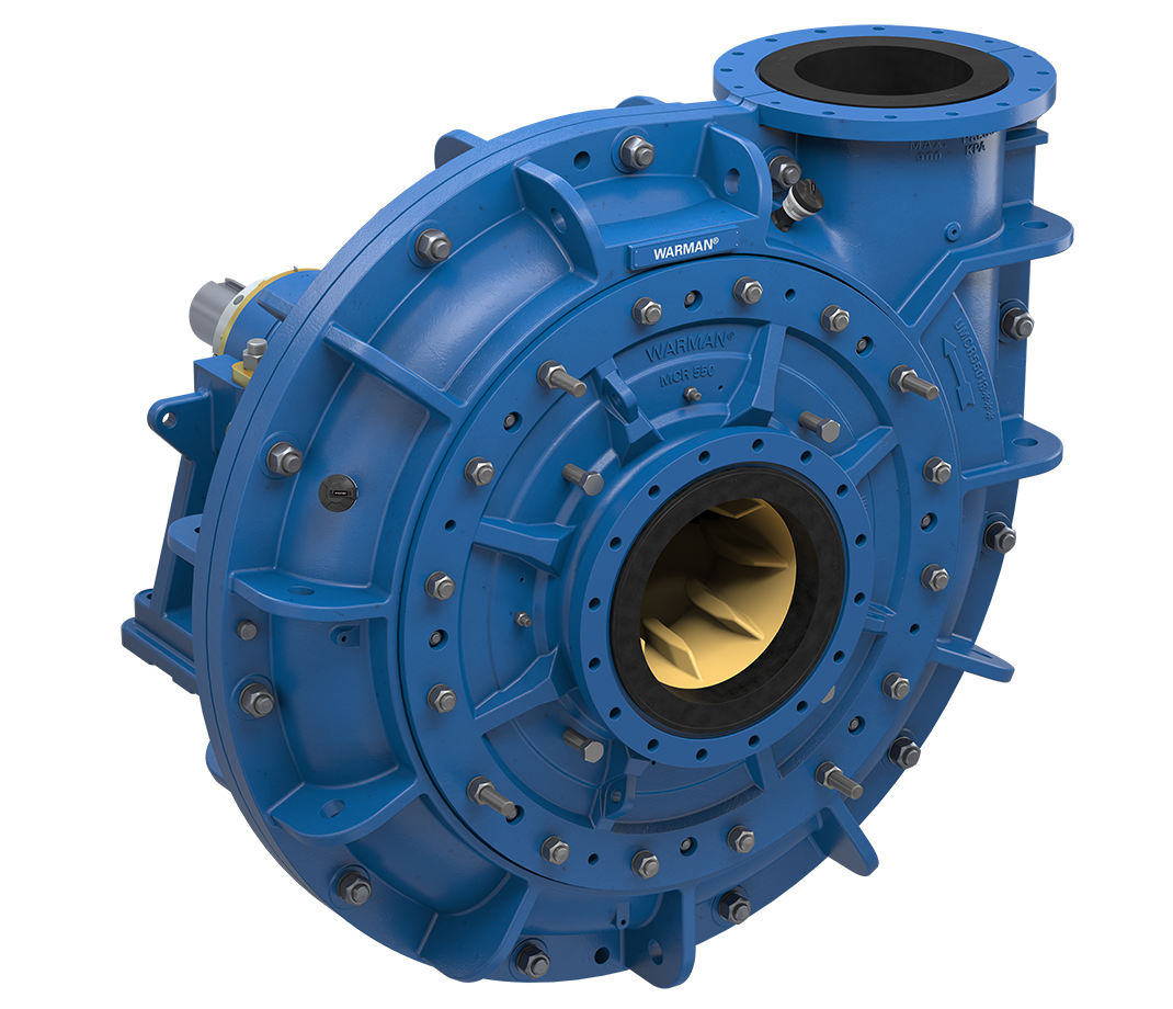
The multistage pump is mainly composed of four parts: stator, rotor, bearing and shaft seal:
The pump is directly driven by the prime mover through the elastic coupling. Looking at the pump from the prime mover side, the pump rotates clockwise.
The multi-stage pump is the water inlet and outlet section and the middle section, which are combined together by the tie rod. Its output water pressure can be very large, it is a kind of centrifugal pump, and it also relies on the rotation of the impeller to obtain centrifugal force, thereby material. When the gas density reaches the working range of the mechanical vacuum pump, it is pumped out, so as to gradually obtain a high vacuum. The multi-stage pump realizes suction, compression and exhaust by the change of the volume of the pump cavity, so it is a centrifugal pump with variable volume. When the multi-stage centrifugal pump motor drives the impeller on the shaft to rotate at a high speed, the liquid filled in the impeller is thrown from the center of the impeller along the flow channel between the blades to the surrounding of the impeller under the action of centrifugal force. The pressure and speed are increased at the same time, and they are led to the impeller of the second stage through the flow channel of the guide casing, so that all the impellers and the guide casing flow through successively, and the pressure energy of the liquid is further increased. After stacking each impeller step by step, a certain head is obtained. An appropriate amount of water is installed in the multistage pump body as the working fluid. When the impeller rotates clockwise, the water is thrown around by the impeller. Due to the effect of centrifugal force, the water forms a closed ring of approximately equal thickness determined by the shape of the pump cavity. The inner and outer surfaces of the lower part of the water ring are just tangent to the impeller hub, and the upper inner and outer surfaces of the water ring are just in contact with the tip of the blade (in fact, the blade has a certain insertion depth in the water ring). At this moment, a crescent-shaped space is formed between the impeller hub and the water ring, and this space is divided into several small cavities equal to the number of blades by the impeller. If the bottom 0° of the impeller is taken as the starting point, the volume of the small cavity will change from small to large when the impeller rotates 180 degrees before, and it is connected with the suction port on the end face. At this moment, the gas is inhaled, and when the suction ends, the small cavity will It is blocked from the suction port; when the impeller continues to rotate, the small cavity becomes smaller, so that the gas is compressed; when the small cavity is communicated with the exhaust port, the gas is discharged out of the pump. To sum up, the multi-stage pump relies on the change of the volume of the pump chamber to achieve suction, compression and exhaust, so it is a centrifugal pump that can change the volume.
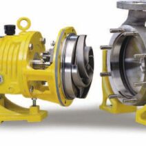
Generally speaking, a multi-stage centrifugal pump has several impellers installed on the same pump shaft, and the outside of the impeller is a liquid guiding device and a pump casing. However, how to install the impeller group in the pump body or take it out from the pump body? There are only two ways. One is to divide the pump body and the guide device horizontally along the axis of the pump shaft to make it into two parts, the upper and lower parts. It is called a horizontally split multistage centrifugal pump; another method is to cut the pump body and the liquid diversion device into several sections along the direction of the pump axis between the impellers with a plane perpendicular to the pump axis, which is called a segmented multi-stage centrifugal pump. stage centrifugal pump. The structures of the horizontally split and segmented multistage centrifugal pumps are described below.
This kind of pump adopts a volute-shaped pump body, and the periphery of each impeller has a corresponding volute chamber, which is equivalent to installing several single-stage volute pumps on the same shaft to work in series, so it is also called a volute multi-stage pump. Since the pump body is horizontally split, the suction port and discharge port are directly cast on the pump body, which is very convenient for maintenance. Just remove the pump cover to expose the entire rotor. When lifting out, it is not necessary to disassemble the connecting pipeline. The impeller of this kind of pump is usually arranged symmetrically with an even number, and most of the axial forces are balanced, so there is no need to install an axial balance device. The flow range of the horizontally split multi-stage pump is 450~1500m'/h, and the highest lift can reach 1800mHz0. Due to the symmetrical arrangement of the impeller and the cross flow channel in the pump casing, it is larger than the segmented multistage pump of the same performance, the casting process is complicated, the positioning requirements of the pump cover and the pump body are high, and the pressure When it is higher, it is difficult to seal the joint surface of the pump cover and the pump body.
At higher pressures, multistage centrifugal pumps are usually used. This pump is a vertical split multistage pump, which consists of a front section, a tail section and several middle sections, which are connected as a whole by four long rod bolts. The number of impellers installed on the pump shaft represents the number of stages of the centrifugal pump. Each impeller in the middle section is equipped with a guide wheel. The function of the guide wheel is basically the same as that of the volute, mainly to convert kinetic energy into static pressure energy. The impeller is generally single-suction, and the suction ports are all directed in one direction. In order to balance the axial force, a balance disc is installed behind the end section, and a balance pipe is used to communicate with the inlet of the front section. During the working process, the rotor can move left and right along the axial direction, and the axial force of the impeller group is balanced by the thrust of the balance disc to maintain the rotor near the equilibrium position. Both ends of the shaft are supported by bearings and placed on the bearing seat, and both ends of the shaft are provided with shaft sealing devices. According to different use occasions, segmented multistage centrifugal pumps can be divided into general segmented multistage centrifugal pumps, medium and low pressure boiler feed pumps, and high pressure boiler feed pumps. The temperature of the liquid transported by the low-pressure boiler feed pump is generally around 110 °C, and its structure is basically the same as that of the general segmented multi-stage centrifugal pump, and most of them can be used with each other. For the medium pressure boiler feed pump, because the working pressure and temperature are higher than those of the low pressure, the requirements for the shaft sealing device are usually higher. In addition to the need for lubrication, the bearings are also cooled by circulating water. In order to insulate heat, some steel plates are used outside the pump to form a cylindrical cover. Some pumps are supported by center support. The temperature of the liquid conveyed by the high-pressure boiler feed pump is 160--170℃, and the outlet pressure is above 15MPa. Considering the influence of temperature changes, most of the rotating parts of the pump are made of alloy materials with the same expansion coefficient. The impeller is installed on the pump shaft, leaving an axial clearance of about 0.50mm at the end to prevent the impeller from being thermally expanded at the beginning of the drive, and the impeller and the impeller squeeze each other, causing the pump shaft to be stretched and damaged. The support of the pump shaft adopts the central support type, so that the thermal expansion of the pump body is radiated from the center of the pump axis after driving, the alignment of the unit will not be damaged, and the rotor will always be in the center position in the pump casing. In order to eliminate the influence of thermal expansion and cold contraction on the concentricity of the unit, the lower part of the high-pressure boiler feed pump shell is provided with longitudinal sliding pins and vertical sliding pins, which are respectively matched with the pin grooves and pin holes on the pump base. The bearing seats of the pump are respectively installed on the front section and the rear section of both ends, and each bearing seat is provided with three adjusting screws to adjust the concentricity between the bearing and the pump casing. The impeller generates axial thrust during operation. There are two measures to balance the axial thrust of the multistage pump: for the horizontal split multistage pump, the impellers are arranged symmetrically, and the impellers are installed in the forward and reverse directions, so that the axial thrusts of the impellers cancel each other and balance each other; For stage centrifugal pumps, since the hour wheels are installed in the same direction, the axial force generated is in the same direction, a thrust balance device is installed at the rear end of the final stage impeller to balance the axial thrust generated by the impellers of all stages. Under normal circumstances, the axial movement of the rotor of the segmented multistage centrifugal pump is 0.10-0.15mm, and the frequency of movement is 10 to 20 times per minute. Therefore, if the medium contains sand or other solid substances during operation, the balance disc and balance ring are easy to wear. In order to resist wear and prolong the service life of parts, the balance disc and balance ring are usually made of wear-resistant metal, such as bronze, gray cast iron, etc.
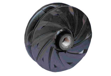
a guide wheel is installed on the outside of each impeller in the middle section of the segmented multistage centrifugal pump. The guide wheel is a fixed disc. Part of the kinetic energy of the liquid is converted into static pressure energy through deceleration, and these liquids are collected and returned in the radial direction and guided to the next stage of the impeller. There are forward guide vanes surrounding the outer edge of the impeller on the front of the seek wheel. There is a reverse guide vane on the back that leads the liquid to the inlet of the impeller of the next stage. After the liquid is thrown from the impeller. Gently enter the forward guide vane in the same direction as the liquid flow velocity, continue to flow outward along the forward guide vane, the speed gradually decreases, and the static pressure increases continuously, and when it reaches the outermost cavity of the guide wheel. The flow velocity is the smallest and the static pressure energy is the highest. After the liquid flows out from the forward guide vane, it bypasses the internal partition plate of the guide wheel in the axial direction, and then flows inward along the reverse guide vane, while reducing the annular flow velocity, and enters the next stage impeller in the axial direction. Compared with the volute, the outer dimension of the guide pulley is smaller, and the efficiency of converting kinetic energy into static pressure energy is also lower. Since there are multiple blades in the guide wheel, when the actual working condition of the pump deviates from the design working condition, the movement trajectory of the liquid flowing out of the impeller is inconsistent with the shape of the guide wheel blades, which causes a large impact loss and reduces the efficiency. Therefore, the centrifugal pump using the guide wheel device has a narrow high-efficiency working area, and the lift and efficiency curves are steeper than those of the volute pump. However, due to the central symmetry of the guide wheel, the radial pressure acting on the rotor will not be generated like the volute, so the multi-stage pump generally uses the volute in the first and last two sections, and uses the guide wheel in the middle section. Due to the complex geometry of the guide wheel, it is generally made of cast iron. Like single-stage centrifugal pumps, multi-stage centrifugal pumps do not have self-priming ability and must be primed before starting. The working principle of various multi-stage centrifugal pumps is that the impeller drives the liquid to rotate at a high speed, so that the liquid generates centrifugal force to obtain energy. In this way, the liquid in the suction chamber on the front side of the first-stage impeller enters the first-stage impeller. After the impeller does work on it, it is thrown into the first-stage guide wheel. After the first-stage guide wheel turns energy, it enters the second-stage impeller. The second-stage impeller continues to work on it, and then enters the second-stage guide wheel, and so on, until it is thrown out from the final impeller, collected by the volute, and sent to the discharge port for discharge.
Bookmark
Daniel Féau processes personal data in order to optimise communication with our sales leads, our future clients and our established clients.


This site is protected by reCAPTCHA and the Google Privacy Policy and Terms of Service apply.