


EUR
en
Copyright 2015, BlackHawk Industrial, 1501 SW Expressway DR., Broken Arrow, OK.74012. BlackHawk Industrial excludes warranties expressed or implied, as to the accuracy of the data and other information set forth in this publication and does not assume liability for any losses or damage resulting from the use of the materials or application of the data discussed in this publication. BlackHawk Industrial make no warranty, either expressed or implied, other than those stated in its standard Terms and Conditions of Sale (available on request.)
Before Operation
Coupling Alignment
Mounting Hydraulic Motor Adapter
Changing Discharge Nozzle Orientation
Pump Startup
Suggested Piping
Pump Startup
General Operation
Records
Lubrication
During Operation
Maximum Speed
Operation Guidelines
Lip Seal Lubrication
Mechanical Seal
After Operation
Disassembling the pump
Reassembly
Installing Shaft Lip Seals
Setting Impeller Clearances
Installing Packing
Installing Mechanical Seal
Seal Lubricants and Suggested Service Ratings
350.205 Size 4x4x12
350.205 11.25 Size 4x4x12-11.25
350.2056 Size 4x4x12 Hylar Coated
350.1241 Size 6x5x10 Mechanical Seal
350.1242 Size 6x5x10 Lip Seal
350.1243 Size 6x5x11 Mechanical Seal
350.1244 Size 6x5x11 Lip Seal
350.202 Size 8x6x14 Lip Seal (100 HP Frame)
350.2016 Power End Assembly (100 HP Frame)
350.201 Size 8x6x14 Packed (300 HP Frame)
350.203 Size 8x6x14 Lip Seal (300 HP Small Frame)
Legacy to SAP Number Crossover List
SAP Number to Legacy Crossover List
Oil Lube Mechanical Seals
Oil Lube Power Frame Bearing
Close Coupled Electric Motor Versions
This manual covers Duncan Industrial Solutions models 350.205, 350.2056, 350.1241, 350.1242, 350.1243, 350.1244, 350.202, 350.203
Contact BlackHawk Pumps& Services for applications in excess of 100 HP.
Warning : Failure to follow the operating instruction warnings of hazards or unsafe practices could result in injury or death.
Warning : Before attempting to service the pump….. 1. Review the manual. 2. Disconnect or Lock Out all power to the pump to make sure the pump cannot be operated. 3. Close suction and discharge valves. 4. Check the pump temperature to make sure fluid has not overheated. 5. Vent the pump slowly. 6. Drain the pump.
Warning :Do not attempt to pump volatile, corrosive, or flammable materials without reviewing the application with the manufacturer. Misapplication could damage the pump or endanger personnel as a result of pump failure.
Warning :DO NOT OPERATE THE PUMP UNLESS ALL GUARDS ARE IN PLACE. Exposed rotating parts can catch clothing, fingers or tools causing severe injury.
Warning :Do not run pump against a closed discharge for long periods of time. Doing so will cause pump components to deteriorate and could cause the fluid to boil, build pressure, and cause the casing to rupture.
Warning :Use lifting equipment that’s in good operating condition and with adequate capacity to prevent injuries to personnel or damage to equipment.
The pump was inspected and tested before shipment from the factory. Before installation, inspect pump for which may have occurred during shipping such as: 1. Dents, cracks, damaged threads, etc. 2. Carefully read all warning labels.
All Pumps are Right-Hand Rotation Units –
CLOCKWISE when viewed from pump shaft end COUNTERCLOCKWISE when viewed from the suction flange. If rotation is in the wrong direction, shut off and lock out the power and switch any TWO legs of the three-phase circuit. This should correct the rotation. If your pump is single phase unit, shut off and lock out the power and re-connect motor leads as indicated by the diagram inside the motor’s junction box. If the pump is power take off, engine, or hydraulic driven, consult your system designer. Once the proper direction of rotation has been established and the piping has been connected it will be necessary to realign the pump and motor. (This is due to shifting during shipment and loads imposed on the pump by the piping system.)
WARNING: BEFORE STARTING PUMP Disconnect and remove coupling and briefly start motor to verify proper direction of rotation. Operation in the wrong rotation will cause severe damage to the pump. Rotation should be as follows:
DANGER: Make sure all power sources are OFF and Locked Out before performing any service to the pump.
1. Check parallel alignment by placing a straightedge across the two coupling flanges and measuring the maximum offset at various points around the periphery of the coupling without rotating the coupling. If the maximum offset exceeds the figure shown under "Parallel" in Figure 3, realign the shafts. 2. Check angular alignment with a micrometer, vernier, or caliper. Refer to X and X(max) dimensions in Figure 2. Measure from the outside of one flange to the outside of the other at intervals around the periphery of the coupling. Determine the maximum and minimum dimensions without rotating the coupling. These measurements must be within the range of X and X(max). If a correction is necessary, be sure to recheck the parallel alignment.
Maximum RPM and Allowable Misalignment - Inch
SleeveSizeMaximumRPM Parallel Angular X1 X(max) Parallel Angular X
3 9200 0.01 0.035 1.188 1.223 -- -- --
4 7600 0.01 0.043 1.5 1.543 -- -- --
5 7600 0.015 0.056 1.938 1.994 -- -- --
6 6000 0.015 0.07 2.438 2.508 0.01 0.016 2.5
7 5250 0.02 0.081 2.563 2.644 0.012 0.02 2.625
8 4500 0.02 0.094 2.938 3.032 0.015 0.025 3
9 3750 0.025 0.109 3.5 3.609 0.017 0.028 3.562
10 3600 0.025 0.128 4.063 4.191 0.02 0.032 4.125
11 3600 0.032 0.151 4.875 5.026 0.022 0.037 4.938
12 2800 0.032 0.175 5.688 5.863 0.025 0.042 5.75
13 2400 0.04 0.195 6.625 6.82 0.03 0.05 6.688
14 2200 0.045 0.242 7.75 7.992 0.035 0.06 7.812
16 1500 0.062 0.33 10.25 10.58 -- -- --
Types JE, JN, E & N EPDM Type H Hytrel
There are two hydraulic motor adapters available for use with the 350.2016 power frame. The process of mounting the adapter is similar for either model. Figure 2 shows the 278.89831 adapter assembly.
(Legacy 278.89831) Cast Iron hydraulic motor mount.
(104913-46432-247) Steel hydraulic motor mount.
1. Mount the motor adapter (Item 1) to the integral mounting flange on the 350.2016 power frame. Make sure the piloted faces are aligned correctly. (Note: paint may need to be lightly sanded to insure a square fit). 2. Install 4-each 1/2NCx1-1/4” Grade 5 cap screws and lock washers (Items 3 & 4) through integral flange on the power frame and into the motor adapter (Item 1). Tighten securely. 3. Clean pump shaft. Slide 1-7/8” bore coupling half (Item 6) over shaft. DO NOT tighten set screw at this time. 4. Install Hytrel coupling sleeve and motor side coupling on pump side coupling. 5. Install the motor bracket (Item 2) to the hydraulic motor using 1/2NCx1-1/4” Grade 5 cap screws and lock washers (Items 3 & 4). 6. Install hydraulic motor and flange assembly into motor coupling half that’s already mounted on the shaft. 7. Adjust coupling so that a gap of 1.12” is held between the coupling flange faces. 8. First tighten set screws on shaft to 20 – 23 ft.lbs. Then tighten set screw over key to 20 – 23 ft. lbs.
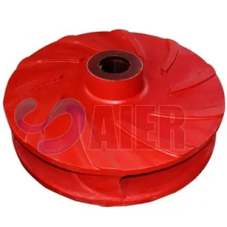
The pump discharge can be easily rotated in 45 degree increments to match piping. This is accomplished removing the mounting feet and moving them to a different position on the pump frame. This avoids removing the pump casing and having to reset impeller clearances. Front and rear feet can even be placed different positions if required.
1. Pump 2. Eccentric Reducer 3. Suction Valve 4. Foot Valve 5. Discharge Valve 6. Suction Pressure Gauge 7. Discharge Pressure Gauge
Suction piping should extend a minimum of 5 times the suction diameter from the first elbow.
Suction pipe size should never be any smaller than pump suction pipe size.
Suction valve should always remain fully open when pump is operating.
Never operate the pump against a closed discharge valve for extended periods of time.
Never use pump to support piping or force misaligned piping into place.
Suction line should be designed to avoid air pockets.
The suction line should always slope downhill away from pump.
Priming the Pump –
1. Open pump suction valve. 2. Vent air from pump and fill with liquid so that fluid covers the eye of the impeller. 3. Start pump and partially open discharge valve. 4. Slowly open discharge valve as discharge pressure stabilizes. 5. If pump fails to prime, shut down pump and repeat steps 1 thru 4. 6. If the pump still fails to prime, shut down pump and inspect for air leaks in the suction line. 7. DO NOT RUN PUMP DRY or with insufficient prime. Catastrophic damage to the mechanical seal or shaft lip seals will occur.
Lubrication –
Bearings - Bearings are grease lubed. They should be lubricated with 4-5 shots of grease after every 12 hours of operation or 5 jobs. The following NLGI2 grease types are approved for use in the pump bearings. 1. Chevron Ulti-Plex Synthetic Grease EP 2. Castrol Optipit 3. Mystic JT6 Hi-Temp #2 4. Lubrication Engineers Almaplex # 1275
Stuffing Box Lip Seals – Stuffing box lip seals are flushed with pressurized oil at no greater than 5 – 7 psig. Seals should be flushed with Dexron III / Mercon automatic transmission fluid.
Environmental Conditions – before operating the pump make sure the following conditions are met:
The pump contains liquid that is above the freezing point.
Pump suction and discharge valves are open.
Maximum Pump Speed – The maximum recommended speeds for the pump are: Model 350.205, 350.2056 - 2600 RPM Model 350.1241, 350.1242, 350.1243, 350.1244 – 1800 RPM Model 350.201, 350.202, 350.203 – 1800 RPM this pump speed is exceeded, bearings may overheat and fail prematurely. Maximum bearing temperature (measured at the test points on bearing frame) should not exceed 220 deg. F. (Please consult manufacturer if these speeds need to be exceeded.)
Operating Guidelines for the Pump –
DO NOT operate the pump dry.
DO NOT operate the pump with the suction valve closed.
DO NOT operate the pump with the discharge valve closed for more than 1 minute.
If the pump must be throttled, use a discharge valve or restriction. NEVER throttle with a suction restriction or the suction valve.
DO NOT operate the pump in reverse. Severe damage to the pump will occur.
Stuffing Box Lip Seals – Stuffing box lip seals are flushed with pressurized oil at no greater than 5 – 7 psig. Seals should be flushed with Dexron III / Mercon automatic transmission fluid. Fluid is supplied by either air pressurized oil supply tank (Legacy part #277.02161 or HP 30034 seal tank) or electric circulating pump system (part # HP 31007).
Mechanical Seals –
The mechanical seal uses the process fluid for lubrication. DO NOT allow the mechanical seal to run dry or mechanical seal failure will occur.
DO NOT close the suction valve while pump is connected to a source of possible high pressure. Pumps are rated for a maximum of 150 PSIG.
If slurry has been pumped, wash out the pump with water for several minutes while pumping at a high rate. If the pump speed can be changed, rapidly accelerate and decelerate the pump from near zero rpm to maximum rpm while washing out.
If the slurry was cement, perform the previous process immediately. If this is not possible, pump other liquids through the pump until it can be thoroughly washed with clean liquids. Failure to flush the pump will allow the cement to solidify inside the pump.
If the pump will be exposed to freezing temperatures before it is used again, remove the drain plugs and empty all liquids from the casing.
1. Mount pump securely to work bench by the rear mounting foot. 2. Attach lifting bail to pump discharge flange and use appropriate lifting equipment to support pump casing. 3. Remove retaining nuts and jam nuts from backside of casing. Remove casing from rotating assembly while supporting casing with appropriate lifting equipment. 4. Place shaft wrench over pump shaft and remove impeller by turning counter clockwise, allowing wrench to strike table. 5. Remove the 4 cap screws that hold the stuffing box in place. Carefully remove stuffing box while allowing power frame to be supported by front mounting foot.
Warning :Use lifting equipment that’s in good operating condition and with adequate capacity to prevent injuries to personnel or damage to equipment.
Warning :Always use personal protective equipment like safety glasses to prevent eye injuries while performing any service work.
6. Remove shaft sleeve. 7. Remove inboard bearing cap and shaft slinger. 8. Place rotating assembly face down and remove rear bearing housing retaining bolts. 9. Lift rear bearing housing, bearings and shaft from frame. 10. Remove rear bearing cap. 11. Remove bearing retaining lock nut. 12. Use a bearing press to remove bearings.
1. Press rear thrust bearings on shaft in a “back to back” configuration.
Bearings can also be installed using a bearing heater or they can be driven on using the appropriate driver. 2. Install lock washer and lock nut. Torque lock nut to 90 ft. lbs. Bend tab on lock washer to lock nut in position. 3. Install lip seal into rear bearing cap using appropriate seal driver. Lip on seal should face towards outside. Install 45 deg. grease zerk in bearing cap. Install O-Ring around rear bearing cap. 4. Install shaft and bearing assembly in rear bearing housing 5. Slide rear bearing cap assembly over shaft and bolt to rear bearing housing using 3/8-16 x 1 hex cap screw, flat washer and lock washer.
6. Install bearing housing O-ring over bearing housing 7. Install inboard bearing on threaded end of shaft. Bearing can be installed facing either direction. Use appropriate driver or press 8. Carefully lower shaft and bearing assembly into frame. Care should be taken to keep shaft and bearings aligned with frame so they don't jam 9. Install 1/2"-13 jam nut on 1/2-13NC x 1-1/2" bolt. Install in threaded hole in bearing housing. Remove guide pin. Install 1/2-13NC x 2" bolt thru same hole in bearing housing and into threaded hole in frame. Make sure bearing housing is bottomed out on frame 10. Install lip seal with lip facing in, on the back side of the bearing cap with appropriate seal driver 11. Install lip seal, with lip facing out, in the front bearing cap with appropriate seal driver. Install grease zerk in 1/8" NPT hole so that connection faces out. Install grease zerk by driving into small hole on opposite side with small hammer 12. Lift power frame assembly and with hoist and place on assembly table
13. Before detaching hoist, place front mounting foot underneath power frame assembly with foot facing toward back of frame. Slide bolt through foot and frame to hold in position. The hoist can now be removed from power frame 14. Install front bearing cap assembly over shaft making sure not to damage lip seals using 3/8"-16NC x 1-1/4 cap screw, washer, and lock washer 15. Install shaft slinger on shaft . DO NOT lubricate shaft or slinger to facilitate installation. Flat side of slinger faces the bearing cap. Leave a gap of about 1/16" to 1/8" off bearing cap 16. Install shaft sleeve O-ring, over shaft and slide to first step in shaft. Carefully slide shaft sleeve over shaft so it seats on O-ring
17. Install three Buna-N lip seals with lips facing the bottom of the stuffing box using appropriate seal driver 18. Install lantern ring set 19. Install one Buna-N lip seal with lip facing bottom of stuffing box using appropriate seal driver. Hand pack with grease working grease into seals and lantern ring 20. Install ring gland with tapped holes facing up 21. Install gland plate using socket head cap screws
22. Tighten cap screws finger tight or torque to 100 in. oz. DO NOT OVER TIGHTEN OR SEALS WILL RUN TOO TIGHT ON SHAFT AND FAIL PREMATURELY 23. Install 1/8" pipe plugs using Teflon sealant in top and bottom 1/8" NPT holes in stuffing box. Install 45 deg. hose adapter in 1/8" NPT hole in stuffing box 180 deg. apart using Teflon sealant. Hand tighten cap onto hose adapter
24. Carefully install stuffing box assembly over shaft , making sure to avoid damaging lip seals. Slide assembly onto shaft until it seats in the pilot dimension on power frame 25. Install one each 5/8-11NC x 1-3/4" cap screw and 5/8 lock washer to hold stuffing box in position.
Make sure stuffing box assembly is supported by pilot dimension on frame and NOT the lip seals. Lip seals can be damaged if the weight of the stuffing box is allowed hang on them 26. Install balance of four each 5/8-11NC x 1-3/4" cap screws and 5/8 lock washers through pump frame into stuffing box and tighten. Use 3 each 5/8-11NC x 2" cap screws and 5/8 lock washer for bottom three holes that attach the foot to the frame. 27. Install O-ring in groove in stuffing box. Spray with WD-40 to facilitate installation of pump casing 28. Coat O-ring grove with Never-Seize or grease and install impeller O-ring in O-ring groove on back side of impeller. Never-Seize or grease will hold o-ring in place during impeller installation 29. Install shaft wrench over keyed end of shaft. Apply never-seize to shaft threads and thread impeller clockwise onto shaft. Make sure bearing housing is bottomed out on frame so shaft extends completely through stuffing box.
30. Using shaft wrench as a stop , spin impeller clockwise allowing wrench to strike the work table. Repeat this process several times until impeller is completely seated on shaft 31. Adjust clearance behind impeller using .014 inch feeler gauge. Use jacking bolts and retaining bolts on rear bearing housing to move impeller in or out. Using .014" feeler gauge check clearance behind impeller by cranking shaft to get a .014" average. Make adjustments as necessary 32. Carefully tighten lock nuts on bearing housing jacking bolts to avoid making changes to impeller clearances 33. Using lifting eye and hoist position pump casing over impeller and stuffing box. Carefully push casing over stuffing box . Be careful not to damage stuffing box O-ring. 34. Install 3/4-10NC x 3" cup point set screws through the unthreaded holes in the 12:00, 3:00, 6:00, 9:00 positions on the frame and into the pump casing. Set screws should extend 2.00 to 2.25 inches from back of pump casing. Coat threads with Never-Seize before installing. Install 3/4-10NC nut on each 3/4-10NC x 3" cap screw . Leave nut loose at this time 35. Install 3/4-10NC x 2" cup point set screws through the threaded holes in the 1:00, 5:00, 7:00, 11:00 positions on the frame and into the pump casing. Coat threads with Never-Seize before installing. Do not screw past the frame flange at this time.
36. Install 3/4-10NC jam nut on each 3/4-10NC x 2" cap screw. Leave jam nut loose at this time 37. Install lifting strap 38. Using .016 inch feeler gauge, adjust casing in or out to get an average of .016" clearance between impeller and suction. Use 3/4-10NC x 2" set screws to push casing out and 3/4-10 nuts to pull casing back. Once an average of .016" is achieved, tighten jam nuts
1. Packing can be used as an alternative to the oil lubricated lips seals. 2. Packing can be cut in the field by firmly wrapping around the shaft sleeve as shown in 3. Rings can then be cut at a 90 deg. angle parallel with the shaft and sleeve 4. Individual rings are then installed in the same squence as the lip seals. 5. Be sure to install the lantern ring in the correct location 6. When installing the individual rings they should be staggered 90 deg from the previous ring so as to avoid creating a leak path 7. Install gland rings and gland plate finger tight. DO NOT OVER TIGHTEN. 8. When starting pump allow packing to leak freely. Slowly tighten the gland bolts until the leak has decreased to approximately 10 – 12 drops per minute. 9. Always allow some leakage from the packing. NEVER STOP LEAKAGE ENTIRELY or damage to the shaft sleeve will occur. 10. Packing should be lubricated with approved grease every 12 operating hours.
1. A mechanical seal is standard on the models 350.1241 and 350.1243. It is available as an option for all other models except the model 350.201. 2. The process fluid lubricates the mechanical seal, so no external lubrication is required. 3. Install 70.81033 roll pin thru the small hole at the bottom of the seal cavity. It should extend 3/32” into the seal cavity 4. Install the stationary side of the mechanical into the bore of the seal cavity.
CAUTION: make sure the notch in the back side of the stationary seal is aligned with the roll pin. Use a soapy water or alcohol hand sanitizing solution to aid in installtion. Use the cardboard divider supplied with the new seal (to protect the seal face), press the stationary seal face into the bore until it bottoms out and the o-ring is seated. 5. Turn seal head over and install 1 each ring of packing in the bottom of stuffing box.
6. Install split gland behind packing. 7. Install gland plate and hand tighten the socket head cap screws If using torque wrench, tighten to between 100 – 120 in. oz. or 6.25 – 7.5 in. lbs. ( DO NOT OVER TIGHTEN. 8. Install shaft sleeve 9. Carefully install seal head assembly onto the power frame 10. Spray seal both faces with WD-40 or similar product to make sure they are free of contaminants. 11. Using a soapy water or alcohol hand sanitizing solution to aid in installtion, slide rotating half of the mechanical seal over the sleeve until the faces meet. Be careful not to “slap” the faces together or they could be damaged. Use caution so as not to cause the rubber bellows to “curl” while pressing the rotating half into position. CAUTION – Do not use oil, grease or other lubicants to slide rotating half of seal on to the sleeve unless they are specifically designed for that purpose. Oil or grease may cause the rubber bellow to slip on the shaft during operation causing the seal to leak. 12. Install the retaining spring.
13. Coat O-ring grove with Never-Seize or grease and install impeller O-ring in O-ring groove on back side of impeller. Never-Seize or grease will hold o-ring in place during impeller installation 14. Install impeller impeller and adjust per instruction on page 29. 15. Seal installation can be facilitated by the use of a seal installation tool. It can be fabricated per the drawing Fig. 16. The tool is usefull during installation and removal of both the stationary and rotating halves of the seal.
Ce menting Lip Seal Press urized Oil
(C-3 or Dexron)
A
Grease B
Packing Grease B
Mechanical Seal None Not
Recommended
Fracturing Slurry Lip Seal Press urized Oil
(C-3 or Dexron)
A
Packing Grease B
Mechanical Seal None Not
Recommended
Mud Circulation Lip Seal Press urized Oil
(C-3 or Dexron)
X
Packing Grease A
Mechanical Seal Clean Flush Liquid X
Water (Fresh) Lip Seal Press urized Oil
(C-3 or Dexron)
A
Packing Grease B
Mechanical Seal None A
Water (Sea) Li p Seal Press urized Oil
(C-3 or Dexron)
A
Packing Grease B
Mechanical Seal None X
Key
A Acceptable Preferred
B Acceptable Secondary
X Untested Performance Unknown
Symptom Potential Causes Corrective Action
1. No Liquid Delivered. a. Pump not primed. Fill pump and pump suction line with water.
b. Speed too slow. Check pump shaft speed with tachometer. Increase speed as needed.
c. Discharge head too high. Make sure there are no obstruction in the discharge line, all valves are open, and that discharge hose is the correct length and diameter. Check with pressure gauge at pump discharge.
d. Suction lift too high or restricted. Remove any obstructions. Make sure liquid viscosity is not to high. Check with vacuum gauge at pump suction. Check suction valves to make sure they are open and unrestricted by debris.
e. Impeller completely plugged. Remove suction cover and clear obstruction.
f. Wrong direction of rotation. If pump is not locked up, check clearances and correct rotation.
g. Viscosity too high (too thick). Reduce liquid viscosity making fluid thinner.
• Lockout or disconnect the power source to pump.
• Allow pump to completely cool if overheated.
• Failure to follow the operating instruction warnings of hazards or unsafe practices could result in injury or death.
2. Not Enough Liquid Delivered. a. Air leak in suction pipe or stuffing box. Adjust packing or repair mechanical seal. Check suction line and connects for leaks.
b. Speed too low. Check pump shaft speed with tachometer. Increase speed as needed.
c. Discharge head higher than anticipated. Make sure there are no obstruction in the discharge line, all valves are open, and that discharge hose is the correct length and diameter. Check with pressure gauge at pump discharge.
d. Suction lift too high. Remove any obstructions. Make sure liquid viscosity is not to high. Check with vacuum gauge at pump suction. Check suction valves to make sure they are open and unrestricted by debris.
e. Impeller partially plugged Remove suction cover and clear obstruction.
f. Not enough suction head Increase liquid level in supply tank.
g. Mechanical defects. Check for worn or damaged impeller or pump casing.
h. Impeller clearances set too wide. Check and adjust impeller clearances.
3. Not Enough Pressure a. Speed too slow. Check pump shaft speed with tachometer. Increase speed as needed.
b. Air in liquid. Adjust packing or repair mechanical seal. Check suction line and connections for leaks. Increase liquid level in supply tank.
c. Mechanical defects. Check for worn or damaged impeller or pump casing.
d. Impeller diameter too small. Remove impeller and install correct diameter impeller.
e. Impeller clearances set too wide. Check and adjust impeller clearances.
4. Pump Works for a While and then Quits.
a. Leak in suction line. Adjust packing or repair mechanical seal. Check suction line and connects for leaks. Increase liquid level in supply tank.
b. Suction plugged or restricted. Remove any obstructions. Make sure liquid viscosity is not to high. Check with vacuum gauge at pump suction. Check suction valves to make sure they are open and unrestricted by debris.
c. Suction lift too high. Remove any obstructions. Make sure liquid viscosity is not to high. Check with vacuum gauge at pump suction. Check suction valves to make sure they are open and unrestricted by debris. Increase liquid level in supply tank.
5. Pump Takes Too Much Power. a. Speed too high. Reduce pump speed.
b. Discharge head lower than rating, pumps too much liquid. Partially close discharge valve to produce more head pressure on pump discharge.
c. Liquid viscosity is too high, liquid heavier than water or both. Reduce liquid viscosity. Reduce flow rate for high fluid weights.
d. V-belts too loose. Adjust belt tension to manufactures specifications. Replace belts if glazed or damaged.
e. Shaft bent. Replace shaft.
f. Impeller rubbing on casing. Check and adjust impeller clearances.
g. Stuffing box packing too tightly adjusted. Do not over tighten packing. Allow liquid to drip thru packing for shaft lubrication.
Bookmark
Daniel Féau processes personal data in order to optimise communication with our sales leads, our future clients and our established clients.


This site is protected by reCAPTCHA and the Google Privacy Policy and Terms of Service apply.