


EUR
en
The almost universal power source in the 5-500hp range, in areas having no mains electricity, is the internal combustion (i.c.) piston engine in either of its two main forms; the petrol (gasoline) fuelled spark ignition engine (s.i .) or the diesel fuelled compression ignition engine, (c.i.). The main reasons for the widespread success of the i.c. piston engine are its high power/weight ratio, compact size and instant start-up capability, which led to its general adoption for powering motor vehicles in particular, and small isolated machinery and boats generally. Mass production, and decreasing fuel prices (until 1973) made small engines based on designs used for motor vehicles both cheap to buy and inexpensive to run. Since the 1973 and 1979 oil crises the trend of declining petroleum prices has generally reversed, although during the mid-1980s we have again a period of declining oil prices which may even last a few years. But even though crude oil prices have again declined (in US dollar terms), petroleum fuels frequently remain in short supply in many developing countries due to inability to finance sufficient oil imports. Almost everywhere the most serious supply shortages are most prevalent in the rural areas, in other words, precisely where farmers are in need of power for irrigation pumping. It is this actual or potential fuel supply problem which makes the alternatives to petroleum fuelled engines, reviewed later in this chapter, worth considering at all; the great versatility of the i.c. engine makes it exceedingly difficult to improve on it from any other point of view.
This is not the book to describe the technicalities of small engines in detail; there are many standard textbooks on this subject and manufacturers and their agents will normally provide detailed information in the form of sales literature. However, when comparing the many available engines, it soon becomes apparent that there is a variety of different types of engine available even at one particular power output.
The two main categories of engine to choose from are c.i. or diesel engines and s.i. or petrol (gasoline), kerosene or 1.p.g. fuelled engines; (1.p.g. - liquified petroleum gas supplied in cylinders and usually primarily propane or butane). C.i. engines ignite their fuel by the heating effect when a charge of air is compressed suddenly enough; finely atomized fuel droplets are sprayed at very high pressure into the cylinder through the injector nozzle at the appropriate moment when the temperature is high enough to cause ignition. Spark ignition engines, on the other hand, work by mixing vapourized fuel with air, compressing the mixture and then igniting it at the correct moment by the electrical discharge of a spark plug set into the cylinder. Diesel engines therefore need to be heavier and more robust in construction to allow the high pressures needed to cause compression ignition to _be_ sustained, and they also require a high pressure metering and injection pump to force the fuel in the right quantities at the right instant in time through the injector nozzle. The diesel injection pump and nozzles are built to a high level of precision and are therefore expensive components despite being mass-produced; they also depend on clean fuel and careful maintenance for reliable operation. Therefore, petrol/gasoline and kerosene engines are inevitably lighter, more compact and usually cheaper than diesels. Although diesel engines are inherently more expensive to manufacture, they compensate for this by being more efficient, more reliable and more long-lasting (but more complicated to maintain in good running order). The main reasons for their better efficiency are firstly, the higher compression ratio allows a diesel to "breathe more deeply", to draw in more air per stroke in relation to the size of combustion space; secondly, fuel injection allows the diesel readily to run on a leaner fuel/air mixture than the equivalent s.i. engine. A spark ignition engine cannot be designed to run at such a high compression ratio, or the fuel/air mixture would ignite prematurely causing "knocking" or "pinking". Another less well known advantage of the diesel is that diesel fuel is 18% "richer" in energy than gasoline per litre (mainly due to its higher density); indicates the calorific value of the three main petroleum fuels. Since fuel is generally bought by the litre (or some equivalent volume measure such as gallons), rather than by its weight or by its energy value, you can buy 18% more energy per litre of diesel than with petrol (gasoline). Therefore the diesel is generally to be preferred as a power source, in terms of efficiency and reliable operation for long periods per day. For pumping applications, however, the choice of petrol or diesel relates largely to the scale of pumping required. Where a small, lightweight, portable system is needed which will only be used for one or two hours per day, and where simplicity of maintenance is important, and where "affordability" matters -i.e. the farmer has only the minimum capital to invest, then an i.e. gasoline or kerosene engine may be best and for that reason is frequently used. It should be explained that the kerosene engine is similar to a petrol (gasoline) engine; indeed most kerosene engines need to be started and warmed up on petrol, because kerosene will not vapourize adequately in a cold engine. Many kerosene engines have a separate compartment in their fuel tank for a small supply of petrol and a tap to switch the fuel supply from petrol to kerosene once the engine is warm; it is also important to switch back to petrol a few moments before stopping the engine so that the carburettor float chamber is refilled with petrol ready for the next time the engine has to be started. Some farmers start kerosene engines simply by pouring petrol into the air intake, but this practice is not to be recommended as it can cause a fire. The advantage of a kerosene engine is that kerosene is normally available for agricultural purposes in an untaxed, subsidised or lightly taxed form and it also contains approximately 10% more energy per litre than petrol. The latter also usually carries a motor fuel tax in most countries as it is mainly used for private cars; therefore fuel costs for kerosene are generally much lower than for gasoline. Kerosene is also much less dangerous to store in quantity as it is much less easily ignited. The kerosene supply is also used for lighting and cooking fuel in many rural households and is therefore a more generally useful fuel. compares the general attributes of the three main i.e. engine options. It should be noted that diesels are sub-divided into two main categories; "low speed" and "high speed". The former run at speeds in the 450-1200 rpm range and tend to be much heavier and more expensive in relation to their power rating than the latter which typically run at speeds in the 1200-2500 rpm range. The slow speed diesel tends to have a much longer operational life and to be better suited to continuous operation, or long duty cycles, but its initial purchase cost is much higher.
A general characteristic of all i.c. engines is that the smaller and lighter they are for a given power output, the lower will be their initial purchase price (which correlates to some extent with the weight) and the shorter will be their useful life. This is because a high power/weight ratio is normally achieved by running an engine at high speed; the faster an engine runs, the more air/fuel mixture it can consume and the greater will be the energy delivered. However, a faster machine will wear out quicker simply because its moving and rubbing components travel further in a given number of hours of use. There is therefore a tradeoff between heavy, expensive and slow engines on the one hand, and cheap and fast ones of the same power rating. Therefore, small, lightweight engines are recommended for such duties where portability and low first cost are important. In most cases, especially if the engine is part of a fixed installation and to be used for lengthy duty cycles, it will generally be worth investing in a suitably heavy and slower machine in the interests of achieving better reliability and a longer operational life. In general light s.i. engines are restricted to duties requiring less than 500 hours running time per season.
If an engine is run continuously at its Rated Power, premature wear will occur. All engines therefore require to be derated from the manufacturer's rated power (which is the maximum power output the engine can achieve for short periods). Small engines are usually derated to about 70-80% of their rated power; eg. a 5kW rated engine will be necessary to produce a continuous 3.5-4.0kW. The main reason for derating an engine is to prevent premature wear, but also the optimum efficiency for most engines is achieved at a speed corresponding to about 70-80% of its speed for maximum power. Therefore, derating an engine usually improves its specific fuel consumption (the fuel required per unit of output). Further derating is necessary at high altitudes or at high ambient temperatures; recommendations to this effect are usually made by the manufacturer. Typically a further 10% derating is recommended for each 1 000m above sea level, plus 1% for each 5°C temperature rise above 16°C at the engine air intake. Therefore at 2 000m altitude and an ambient temperature of 26°C it would be necessary to derate an engine by say, 0.8 (generally) times 0.8 (for altitude) times 0.98 (for temperature) which totals .63 or 63% of rated power which would be the correct load to apply. Therefore a 2 O00W load would require an engine nominally rated at 2 000/0.63 or 3.2kW (4.3bhp) under those conditions. Excessive derating is to be avoided, as (particularly with diesels) running at a fraction of the design power tends to cause coking of the cylinder. Also, the engine efficiency will of course be much poorer than normal under such conditions.
Both s.i. and c.i. engines can be designed to run so that ignition takes place either every other revolution, (four-stroke or four-cycle) or every revolution (two-stroke or two-cycle). The four-stroke s.i. engine tends to be more efficient as the "non-firing" revolution gives more time for inducing a fresh charge of fuel and also for effectively driving out the exhaust gases from the previous firing stroke (s.i. two-strokes tend to be less well scavenged of exhaust). Two-stroke diesels do not suffer an efficiency penalty in the same way, but are not generally available in the small size range of relevance for small scale irrigation. The two-stroke s.i. engine tends to be high revving and lightweight; it usually has fewer components than a four-stroke and therefore is cheaper to manufacture; typical applications are as moped engines. They are less suitable for irrigation pumping than four-strokes as they use more fuel and wear out more quickly. Most s.i. two-strokes use the downward movement of the piston into the crankcase to displace the air/fuel mixture into the cylinder; in which case it is not possible to lubricate the engine with a separate oil supply and the lubricant is mixed with the petrol, (two-stroke mix). This removes the need for oil changes, but is wasteful of lubricant, tends to cause a smoky exhaust, causes the need for more frequent "decokes" (de-carbonization of the cylinder head) and introduces a risk of damage caused by an inexperienced operator failing to mix sufficient lubricating oil with the fuel, or using the wrong type of oil. For these reasons, two-stroke s.i. engines are tending to be phased out and replaced by four strokes.
About one third of the heat produced when the fuel is burnt has to be dissipated through the walls of the cylinder and through the cylinder head; the two methods generally used for removing this heat and preventing the cylinder overheating are either by surrounding the cylinder with a water jacket which has water circulated through it and a separate radiator, or by having many cooling fins on the cylinder (to increase its effective surface area), and blowing air over the fins with a fan driven off the engine. A few small, low-powered, and old fashioned low-speed stationery engines have a water jacket with an open top and keep cool simply by boiling the water, which needs to be topped up from time to time, but most modern liquid cooled engines have their coolant circulated by a pump just like car engines. Each method of cooling has its pros and cons. Water cooled engines tend run slightly quieter and their engine temperature is more easily regulated through the use of a thermostat, than with air cooling. However, with water cooled engines, internal corrosion can occur and also water can leak out, evaporate or freeze. This last problem can be prevented by the use of anti-freeze (ethylene glycol) mixed with the cooling water in winter; most anti-freezes also contain corrosion inhibitor and are therefore useful to add to the cooling water even in climates where freezing is not likely to occur. Loss of coolant generally causes severe engine damage if the engine is allowed to continue running in that condition; various safety devices are available either to warn of overheating (caused by loss of coolant or for any other reason) and in some cases to automatically cut off the fuel supply and stop the engine. Air cooled engines obviously cannot lose their coolant, but it is important to ensure that their cooling fins do not get clogged with dust or dirt and that any cooling fan (when fitted) is clean and functioning correctly.
The smallest engines usually have a single cylinder, mounted vertically above the crankshaft, as this is convenient for access to the main engine components and also allows an oil sump to be conveniently located where oil can drain down to it from the cylinder. A large flywheel is needed to smooth the output from a single cylinder engine as excessive vibration can cause problems with parts resonating and fatiguing and nuts and bolts working loose. Single cylinder low speed diesels need particularly heavy flywheels because they have large heavy pistons and connecting rods which run at low speeds; traditional designs are "open flywheel" while the more modern style of high-speed diesel engine usually has an internal enclosed flywheel. With larger sizes of engine it becomes feasible to have two or more cylinders. Twin cylinder engines have a smoother power output because the cylinders fire alternately and partially balance each other. Multi-cylinder engines therefore run more smoothly and quietly than ones of the same power with fewer cylinders, but the more cylinders there are the more components are involved, so obviously a multi-cylinder engine will be more expensive and more complicated to overhaul and maintain.
Most small pumping systems have a hand crank starter or a pull chord (recoil) starter (the former is more common with small diesels and the latter with small petrol engines). Diesels often include a decompression valve to aid starting, in which a cylinder valve can be partially opened to release the pressure when the piston comes up on the compression stroke, allowing the engine to be hand wound up to a certain speed, when the decompression valve is suddenly closed and the momentum of the flywheel(s) carries the machine on sufficiently to fire the engine and start it off. Larger engines often have an auxilliary electrical system and a battery with an electric starter; (spark ignition engines generally need a battery to run the ignition, although very small s.i. engines use a magneto which generates and times the spark from the rotation of the engine). Engines fitted with electrical systems or engines coupled to generators can have various electrical controls to warn of or to prevent damage from overheating, loss of lubricant, etc. Some of these options, although sophisticated, are not expensive and are therefore a sound investment. A vital, and often neglected accessory is the air filter, especially in dusty climates. Usually there is a choice of paper element filter (as used on most cars) where the paper element needs to be regularly replaced when clogged with dust or torn or, alternatively, an oil bath filter. The latter is slightly more expensive, but much more effective and practical in an agricultural context, since at a pinch even old engine oil can be used to refill it. A worn or malfunctioning air filter can greatly reduce the useful life of an engine, a fact which is often not fully understood by farmers judging from the number of engines that can be found running without any air filter at all.
The smallest engines are supplied mounted on skids or in a small frame and therefore need no installation other than coupling their pump to the water conveyance system. But larger machines, and many diesels, need to be properly installed, either on a concrete pad or on a suitable trolley or chassis. Most manufacturers will provide a detailed specification, when necessary, for the foundations of any engine driven pumping system; this should be accurately adhered to. The engine often needs to be installed in a small lockable building for security. It is essential, however, that any engine house is well ventilated and that the exhaust is properly discharged outside. This is not only to avoid the serious danger of poisoning the user with exhaust gases, but also to ensure the engine does not overheat. Similarly, engines with direct coupled centrifugal pumps sometimes need to be installed in a pit in order to lower them near enough to the water level to avoid an excessive suction lift. Considerable care is needed with such installations to ensure that neither exhaust nor oil fumes will fill the pit and poison anyone who enters it; carbon monoxide in i.c. engine exhaust emissions can, and frequently does, cause fatal accidents. Care is also needed to ensure that the water level will never rise to a level where it could submerge the engine.
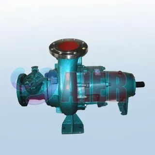
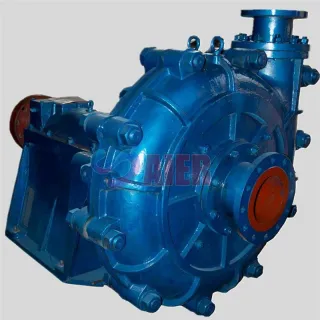
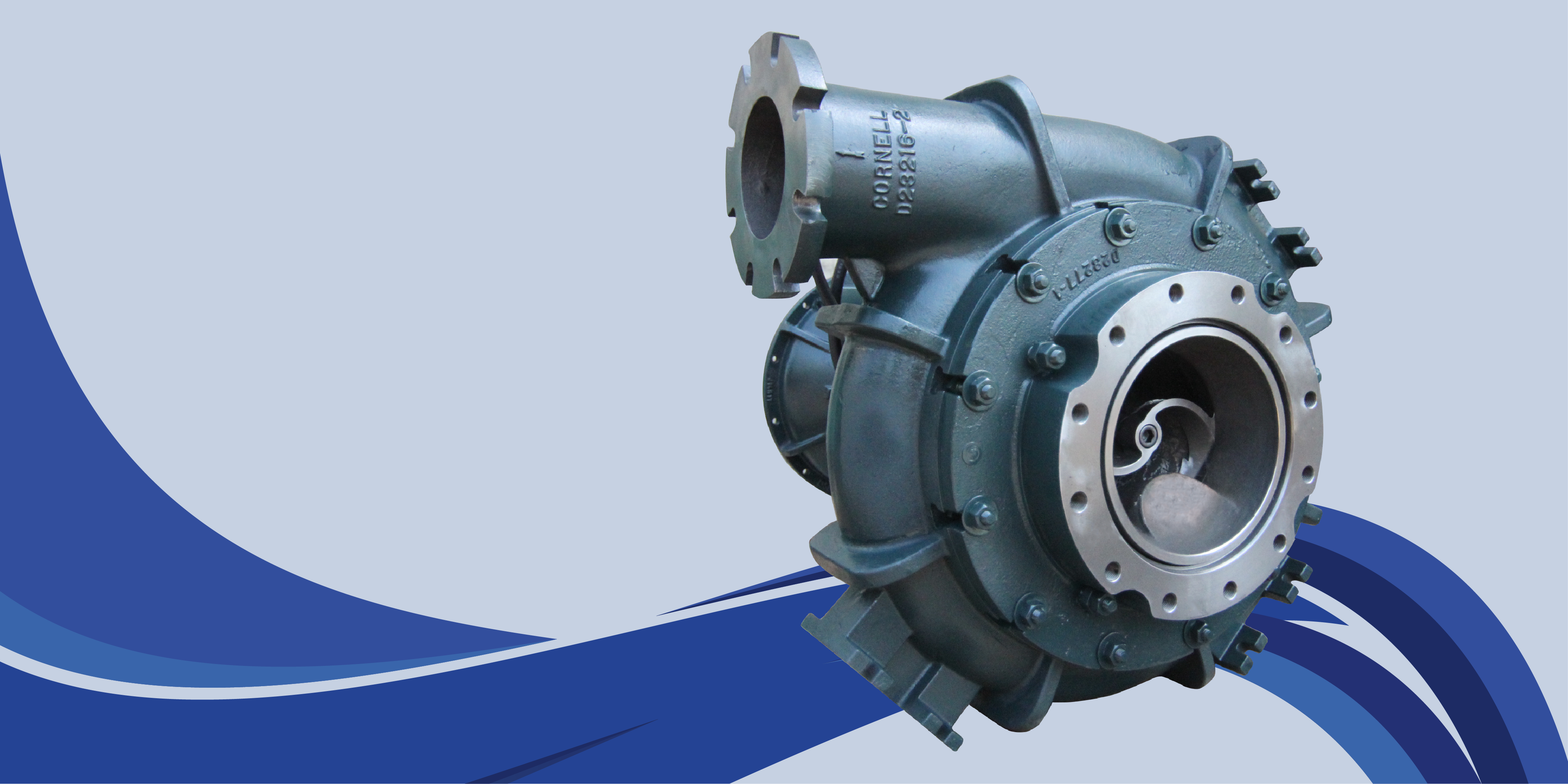
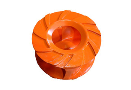
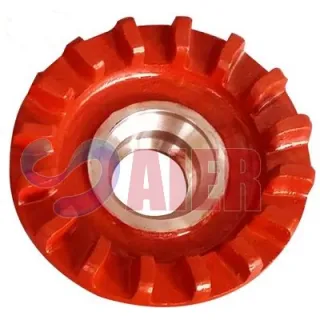
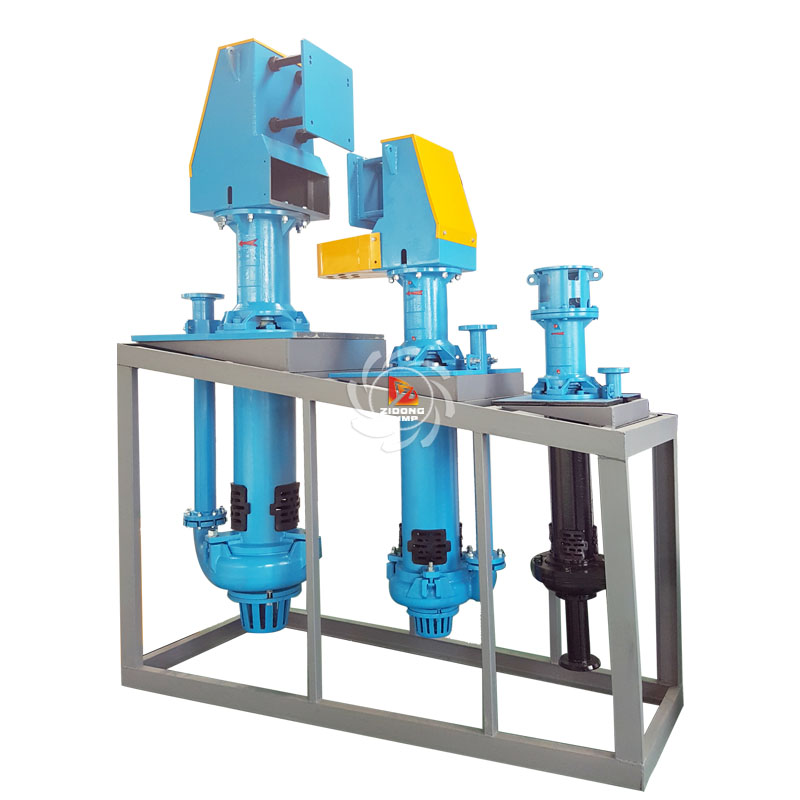
This is a controversial subject where little reliable data on actual field performance exists in the literature. A few field tests have been carried out on "typical" irrigation pumping systems, and in some cases surprisingly poor efficiencies were achieved. For example, Jansen [32] reported on tests on three kerosene fuelled small pumping sets in the 2-3 bhp range in Sri Lanka; total system efficiencies in the range 0.75-3.5% were recorded although engine/pump efficiencies (without a pipeline) were in the range from 2.6-8.8%. Excessive pipeline friction losses obviously caused the very poor system performance. Unfortunately there is good reason to assume such losses are quite common. Many of the reasons for poor performance can be corrected at little cost _once_ it is recognized that a problem exists, but unfortunately, it is easy to run an inefficient pumping system without even realizing it, because the shortfall in output is simply made up by running the engine longer than would otherwise be necessary. indicates the principle components of a small engine pumping system and the range of efficiencies that can typically occur for each. Some explanation of these may give an insight into how such poor total system efficiency can sometimes occur, and by implication, what can be done to. improve it. Firstly, fuel spillage and pilferage could perhaps result in, anything from 0-10% of the fuel purchased being lost; i.e. 90-100% of fuel purchased may be usefully consumed as indicated in the figure. Spillage can occur not only when transferring fuel, but due to leaky storage or very frequently due to either a leaky fuel line on the engine or leaky joints especially on the high pressure lines of a diesel engine; well established fuel stains on the ground ought to give warning that something is wrong with fuel management. As the value of fuel increases, pilferage becomes increasingly a problem. One standard 200 litre drum of fuel is worth typically US $50-100; a small fortune in many developing countries. Most basic thermodynamics textbooks claim that s.i. engines tend to be 25-30% efficient, while diesels are 30-40% efficient. Similarly, manufacturers' dynamometer tests, with optimally tuned engines, running on a test-bed, (often minus most of their accessories), tend to confirm this. However, such figures are optimistic in relation to field operations. The difference between theory and reality is greatest with the smallest sizes of engines, which are inherently less efficient than larger once, and the text-book figures quoted above really only apply to well tuned engines of above 5-10kW power rating. The smallest tow-stroke and four-stroke s.i. engines also tend to vary in quality, engine to engine, and can easily be as poor and only 10% efficient at around 1kW power rating. Small diesels (the smallest are generally about 1.5 to 2kW) will probably be better than 20% efficient as engines, but components like the injection pump, cooling fan and water circulating pump (all parasitic energy consumers) can reduce the fuel-to-useful-shaft-power efficiency to around 15% (or less) for the smallest engines. This large drop is because the parasitic accessories take proportionately more power from very small engines. Obviously engines are also only in new condition for a small part of their, lives, and on average are worn and not well tuned, which also undermines their efficiency. Hence depending on size, type and quality plus their age and how well they are maintened, engines may in reality be at best 35% efficient and at worst under 10% efficient. The next source of loss is any mechanical transmission from the engine to the pump. In some cases the engine is direct coupled to the pump, in which case the transmission losses are negligible, but if there is any substantial change of speed, such as a speed-reducer and gearbox to drive a reciprocating borehole pump, then the transmission can be as low as 60% efficient, particularly with small systems of less than 5kW, where geaz box losses will be relatively large in relation to the power flow. As discussed in the previous section, the most common type of pump used for irrigation with a small engine will be a centrifugal pump, either direct coupled or belt driven, usually working on suction; (eg. and ). If properly installed, so that the pump is operating close to its optimum head and speed, the pump efficiency can easily exceed 60% and possibility be as high as 80% with bigger pumps. However there is a lot of scope for failing to achieve these figures; bad impeller designs, worn impellers with much back-leakage, operating away from the design flow and head for a given speed will all have a detrimental effect and can easily singly, or in combination, pull the efficiency down to 25% or less. Given a reasonably well matched and well run system, pump efficiencies will therefore be in the 40-80% range, but they could easily be worse (but not better) than this range. It is often not appreciated that the choice of delivery pipe can have a profound effect on system performance. Engines can deliver very high volumes at low head, so pipe friction can grossly increase the total head across the pump, particularly with long delivery lines at low heads. When this happens, it is possible for the total head to be several times the static head, which multiplies the fuel requirement proportionately. allows this to be quantified; eg. even a small portable petrol engine pump will typically deliver over 360 l/min or 6 l/s through 5m head (600W hydraulic output). The friction loss for each 100m of delivery pipe with this flow and head will approximately as follows: pipe nominal diameter:2" (50mm)21/2"(65mm)3" (80mm) friction head (m/100m):20m 5m 2m from this, the pipe line efficiency for various lengths of pipe with the above diameters is as follows: total pipe length efficiencies in % for 5m static head and pipe diameters shown 2in 21/2in 3in 10m 71 91 96 50m 33 67 83 100m 20 50 71 Quite clearly, when pumping at such low heads, it is easy to achieve total heads that are several times the static head, giving rise to pipeline efficiencies as poor as 20% when 100m of 2" pipe is used; (i.e. in that case the pumped head is five times the static head so that five times as much fuel is needed compared with a 100% efficient pipeline). The situation gets proportionately less serious at higher static heads, because it is the ratio of pipe friction head to static head that matters; for example, at 20m static head the above example would give the same friction head of 20m which although unacceptably high would at least imply 50% rather than 20% pipeline efficiency. It is a common mistake to use pipework which is too small in diameter as a supposed "economy" when larger pipe can often pay for itself in saved fuel within months rather than years. Also, some pumps which have a 2in discharge orifice may actually need a 3in pipeline if some distance is involved, yet uninformed users will usually use a pipe diameter to, match the pump orifice size and thereby create a major source of inefficiency. Incidentally, inch pipe sizes are quoted here simply because they are in fact more commonly used, even in countries where every thing else is dimensioned in metric units. The performance curve in indicates how centrifugal suction pumps can also suffer reduced performance as the suction head increases, mainly due to cavitation, particularly when the suction head is a large fraction of the total head. The figure shows how at 10m total head, 6m suction head causes a 20% drop in output compared with 3m suction head. This is without any reduction in power demand, so the former system is 20% less efficient than the latter, simply due to suction losses. There is therefore a potentially large fuel cost penalty in applying excessive suction lifts (apart from the usual priming problems that can occur). Pipe losses, whether due to friction or suction can therefore cause increased head and reduced flow and will typically have an efficiency in the 30-95% range, as indicated in . The efficiency factors discussed so far apply to the hardware, while it is being run and water is being usefully applied to the field. Inevitably the system needs to run when water is not being usefully applied. For example, when starting up, any engine will often be run for a few minutes before the farmer can arrange the discharge to reach the correct part of the field, and water will be wasted. Similarly when rearranging the distribution system to deliver water to another part of the field, some wastage may occur. There is therefore a factor relating to the type of water distribution system and to the management skill of the farmer at applying the pumped water for as large a fraction of the time it is being pumped (or the engine is running) as possible. Even moderately bad management could cause 20% loss compared with ideal usage, and really bad management can be much worse, so this efficiency is taken as ranging from 80-100% for the purpose of . When all the worst efficiencies suggested in are compounded, they yield a theoretical worst total efficiency of 0.5% (which Jansen [32] and others have confirmed) while the best factors in compounded together give 27%. The "best" figure is only even theoretically feasible however for a larger diesel (over 5kW), driving a pump at 10-20m (or higher) head, which is rather higher than usual for most irrigation applications. Most smaller engine pumped irrigation systems therefore in practice probably achieve 5 to 15% total efficiency, with larger diesels operating at higher heads being towards the top end of this range and small kerosene or petrol engines at low heads being at (or below) the bottom. The operator should probably be satisfied if a small diesel system achieves 10-15% efficiency and a small petrol or kerosene fuelled system achieves 5-10%. It may be very worthwhile for any reader to investigate the actual efficiency of any engine pumping system they may be responsible for, (by comparing fuel consumption against hydraulic energy output) so that if it is below par steps may be taken to find the causes and to correct them.
The difference between internal and external combustion engines, as their names suggest, is that the former burn their fuel within the power cylinder, but the latter use their fuel to heat a gas or a vapour through the walls of an external chamber, and the heated gas or vapour is then transferred to the power cylinder. External combustion engines therefore require a heat exchanger, or boiler to take in heat, and as their fuels are burnt externally under steady conditions, they can in principle use any fuel that can burn, including agricultural residues or waste materials There are two main families of external combustion engines; steam engines which rely on expanding steam (or occasionally some other vapour) to drive a mechanism; or Stirling engines which use hot air (or some other hot gas). The use of both technologies reached their zeniths around 1900 and have declined almost to extinction since. However a brief description is worthwhile, since: 1. they were successfully and widely used in the past for pumping water; 2. they both have the merit of being well suited to the use of low cost fuels such as coal, peat and biomass; 3. attempts to update and revive them are taking place. and therefore they may re-appear as viable options in the longer term future. The primary disadvantage of e.c. engines is that a large area of heat exchanger is necessary to transmit heat into the working cylinder(s) and also to reject heat at the end of the cycle. As a result, e.c. engines are generally bulky and expensive to construct compared with i.c. engines. Also, since they are no longer generally manufactured they do not enjoy the economies of mass-production available to i.e. engines. They also will not start so quickly or conveniently as an i.c. engine; because it takes time to light the fire and heat the machine to its working temperature. Due to their relatively poor power/weight ratio and also the worse energy/weight ratio of solid fuels, the kinds of applications where steam or Stirling engines are most likely to be acceptable are for static applications such as as irrigation water pumping in areas where petroleum fuels are not readily available but low cost solid fuels are. On the positive side, e.c. engines have the advantage of having the potential to be much longer-lasting than i.c. engines (100 year old steam railway locomotives are relatively easy to keep in working order, but it is rare for i.c. engines to be used more than 20 years or so. E.c. engines are also significantly quieter and free of vibrations than i.c. engines. The level of skill needed for maintenance may also be lower, although the amount of time spent will be higher, particularly due to the need for cleaning out the furnace. Modern engineering techniques promise that any future steam or Stirling engines could benefit from features not available over 60 years ago when they were last in general use. Products incorporating these new developments are not yet on the market, but R&D is in hand in various countries on a limited scale; however it will probably be some years before a new generation of multi-fuel Stirling or steam powered pumps become generally available.
Only a limited number of small steam engines are available commercially at present; most are for general use or for powering small pleasure boats. A serious attempt to develop a 2kW steam engine for use in remote areas was made by the engine designers, Ricardos, in the UK during the 1950s (see Fig. 157). That development was possibly premature and failed, but there is currently a revival of interest in developing power sources that can run on biomass-based fuels (as discussed more fully in Section 4.10). However, small steam engines have always suffered from their need to meet quite stringent safety requirements to avoid accidents due to boiler explosions, and most countries have regulations requiring the certification of steam engine boilers, which is a serious, but necessary, inhibiting factor. The principle of the steam engine is illustrated in . Fuel is burnt in a furnace and the hot gases usually pass through tubes surrounded by water (fire tube boilers). Steam is generated under pressure; typically 5 to 10 atmospheres (or 5-10bar). A safety valve is provided to release steam when the pressure becomes too high so as to avoid the risk of an explosion. High pressure steam is admitted to a power cylinder through a valve, where it expands against a moving piston to do work while its pressure drops. The inlet valve closes at a certain point, but the steam usually continues expanding until it is close to atmospheric pressure, when the exhaust valve opens to allow the piston to push the cooled and expanded steam out to make way for a new intake of high pressure steam. The valves are linked to the drive mechanism so as to open or close automatically at the correct moment. The period of opening of the inlet valve can be adjusted by the operator to vary the speed and power of the engine. In the simplest types of engine the steam is exhausted to the atmosphere. This however is wasteful of energy, because by cooling and condensing the exhausted steam the pressure can be reduced to a semi-vacuum and this allows more energy to be extracted from a given throughput of steam and thereby significantly improves the efficiency. When a condenser is not used, such as with steam railway locomotives, the jet of exhaust steam is utilised to create a good draught for the furnace by drawing the hot gases up the necessarily short smoke stack. Condensing steam engines, on the other hand, either need a high stack to create a draught by natural convection, or they need fans or blowers. Steam pumps can easily include a condenser, since the pumped water can serve to cool the condenser. According to Mead [13], (and others) the typical gain in overall efficiency from using a condenser can exceed 30% extra output per unit of fuel used. Condensed steam collects as water at the bottom of the condenser and is then pumped at sufficient pressure to inject it back into the boiler by a small water feed pump, which is normally driven off the engine. A further important advantage of a condensing steam engine is that recirculating the same water reduces the problems of scaling and corrosion that commonly occur when a continuous throughput of fresh water is used. A clean and mineral-free water supply is normally necessary for non-condensing steam engines to prolong the life of the boiler. The most basic steam engine is about 5% efficient (steam energy to mechanical shaft energy - the furnace and boiler efficiency of probably between 30 and 60% needs to be compounded with this to give an overall efficiency as a prime-mover in the 1.5 to 3% range). More sophisticated engines are around 10% efficient, while the very best reach 15%. When the boiler and furnace efficiencies (30-60%) plus the pump (40-80%) and pipework (40-90%) are compounded, we obtain system efficiencies for steam piston engine powered pumps in the 0.5 to 4.5% range, which is worse, but not a lot worse than for small s.i. internal combustion engines pumping systems, but allows the use of non-petroleum fuels and offers greater durability.
This type of engine was originally developed by the Rev. Robert Stirling in 1816. Tens of thousands of small Stirling engines were used in the late nineteenth and early twentieth century, mainly in the USA but also in Europe. They were applied to all manner of small scale power purposes, including water pumping. In North America they particularly saw service on the "new frontier"; which at that time suffered all the problems of a developing country in terms of lack of energy resources, etc. Rural electrification and the rise of the small petrol engine during and after the 1920s overtook the Stirling engine, but their inherent multi-fuel capability, robustness and durability make them an attractive concept for re-development for use in remote areas in the future and certain projects are being initiated to this end. Various types of direct-action Stirling-piston water pumps have been developed since the 1970s by Beale and Sunpower Inc. in the USA, and some limited development of new engines, for example by IT Power in the UK with finance from GTZ of West Germany is continuing. Stirling engines use pressure changes caused by alternately heating and cooling an enclosed mass of air (or other gas). The Stirling engine has the potential to be more efficient than the steam engine, and also it avoids the boiler explosion and scaling hazards of steam engines. An important attribute is that the Stirling engine is almost unique as a heat engine in that it can be made to work quite well at fractional horsepower sizes where both i.c. engines and steam engines are relatively inefficient. This of course makes it of potential interest for small scale irrigation, although at present it is not a commercially available option. To explain the Stirling cycle rigorously is a complex task. But in simple terms, a displacer is used to move the enclosed supply of air from a hot chamber to a cold chamber via a regenerator. When most of the air is in the hot end of the enclosed system, the internal pressure will be high and the gas is allowed to expand against a power piston, and conversely, when the displacer moves the air to the cool end, the pressure drops and the power piston returns. The gas moves from the hot end to the cold end through a regenerator which has a high thermal capacity combined with a lot of surface area, so that the hot air being drawn from the power cylinder cools progressively on its way through the regenerator, giving up its heat in the process; then when cool air travels back to the power cylinder ready for the next power stroke the heat is returned from the regenerator matrix to preheat the air prior to reaching the power cylinder. The regenerator is vital to achieving good efficiency from a Stirling engine. It often consists of a mass of metal gauze through which air can readily pass, [33], [34 ]. Some insight into the mechanics of a ' small Stirling engine can be gained from Fig. 103, which shows a 1900 vintage Rider-Ericsson engine. The displacer cylinder projects at its lower end into a small furnace. When the displacer descends it pushes all the air through the regenerator into the
Bookmark
Daniel Féau processes personal data in order to optimise communication with our sales leads, our future clients and our established clients.


This site is protected by reCAPTCHA and the Google Privacy Policy and Terms of Service apply.